


PW15AHi
20
A2526-4.0 en/de/fr
HBM
IMPORTANT
The PW15AHi CAN bus driver relates to GND. The Master CAN bus driver
must also relate to this GND.
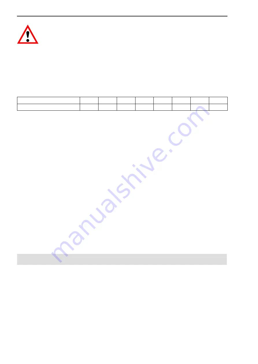
Baud rate and bus cable lengths
The table below gives the maximum cable lengths for the CANopen bus, subject to
the baud rate:
Baud rate [kBits/s]
10
20
50
125
250
500
800
1000
Max. cable length [m]
5000
2500
1000
500
250
100
50
25
The max. cable length is the total line length, calculated from the length of all
the stub lines per node (bus nodes) and the line length between the nodes.
The length of the spur lines per node is limited and depends on the baud rate
being used (see secondary CAN bus documentation:
CiA DS102 V2.0
).
When using the PW15AHi's CAN wiring with CAN_In and CAN_Out lines, the
length of the stub line to the PW15AHi is equal to zero. If only one connection
pair (CAN_In or CAN_Out) is used, the cable length of the PW15AHi counts as
the stub line.
Setting the address
The address is set via the bus:
CAN bus: 1...127 (default on delivery: 63)
Setting the bit rate
The bit rate is set with the fieldbus configuration tool via the bus; the factory
setting is 125 Kbits.
CANopen communication is explained in the Online Help, CANopen Commu
nication description.
7.3
DeviceNet interface
The interface is designed to the DeviceNet specification Release 2.0 ODVA.
Bus configuration
The DeviceNet bus is configured as a 2‐wire CAN bus (CanH and CanL) (see
ISO11898).
It is
essential
for bus termination resistors (each 120
W
) to be
connected at the start and end of the bus.
The PW15AHi does not contain a
bus termination resistor (line termination). The bus wiring structure was chosen
to minimize the length of the stub lines.
Содержание PW15AHi
Страница 2: ...English Page 3 0 24 Deutsch Seite 25 0 46 Fran ais Page 47 0 68...
Страница 69: ...69 PW15AHi A2526 4 0 en de fr HBM...
Страница 70: ...PW15AHi 70 A2526 4 0 en de fr HBM...
Страница 71: ......