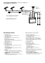
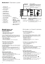
HAUTAU RAZ K Скачать руководство пользователя страница 8

8

Anschlussplan / 

Terminal connection diagram 

Anwendungsbeispiel / 

Application example

Zu /

 Close

Auf /

 Open

6

5

4

3
2

1

6

5

4

3
2
1

4
3

2

1

2

1

L

10k

10k

10k

2k 0,5 W

W

ind sensor WM/H 10 and/or 

Rain sensor REM/H 10

Windmelder WM/H 10 und/oder  Regenmelder REM/H 10

Potentialfrei von der  Rauchabzugszentrale an zentrale Leitstelle Störung

Potential-free from  smoke and heat exhaust control unit to central  control station malfunction

Schlüsseltaster ST 010

Key pushbutton ST 010

Windgeber/Regenmelder WREM/H 10

W

ind transmitter/Rain sensor WREM/H 10

Windgeber WG/H 10

W

ind transmitter WG/H 10

Rauchmelder RM 523 Thermomelder TM 523

Smoke detector RM 523 Heat detector TM 523

RM 523 / TM 523

ST 010

WG/H 10

LT

Brandmelde-Zentrale

Central fire alarm system

Regenmelder

Windgeber

Relais fällt bei Störung ab


24 V max. 30 

Wa

tt 

24 V max. 30 

Wa

tt

Relay is deactivated 

by malfunction 

Versorgung 

+

 /


Datenleitung / 

Data line

Versorgung


/

 Supply 

-

Lüftungstaster

Rain sensor

W

ind transmitter

Ventilation pushbutton

Sichtanzeige Auf / 

Display Open

Zu /

 Closed

Auf /

 Opened

Versorgung


/


Supply 

+

Linie /

 Loop

Antriebe

Drives

Melder

Detector

Versorgung


/


Supply 

-


Versorgung


/


Supply 

+

Potentialfrei von der  Rauchabzugszentrale an zentrale Leitstelle Alarm

Potential-free from smoke and heat exhaust control unit to central control station alarm

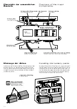
Anschluss Antriebe und  Überwachungsleitung  siehe nächste Seite

Connection of drives  and monitoring line  refer to next page

24 V max. 30 

Wa

tt 

Relais zieht bei Alarm an

24 V max. 30 

Wa

tt 

Relay is activated by alarm

optional für Zuluft-Antrieb

 Lüftungsfunktionen ohne Leitungsüberwachung

optional for drive “supply air”


ventilation functions without line monitorin

g

a) im letzten Feuertaster; b) ist kein Feuertaster FR 900 vorhanden, so sind 2 Z-Dioden 15 V (orange) in der Zentrale wie gezei

gt zu befestigen! 

a) in the last fire pushbutton; b) if no fire pushbutton FR 900 has been installed, install 2 Z-diodes 15 V (orange) in the con

trol unit as shown!

Endwiderstand 10k (Farbcodierung braun, schwarz, orange, gold) für die Leitungsüberwachung in dem einzigen oder letzten Rauchme

lder RM 523 

(oder Thermomelder TM 523) lt. Anschlussplan befestigen. Ist kein Melder vorhanden, so ist der Endwiderstand 10k unter den Klem

men RM + und RM - 

(Melder) in der Zentrale zu befestigen!

Install the 10k terminal resistor (color

-coding brown, black, orange, gold) used for line monitoring in the only or last smoke 

detector RM 523 (or heat detector TM 523)  

according to the terminal connection diagram. If no detector has been installed, install the 10k terminal resistor in the contr

ol unit below terminals 

RM 

and 

RM 

(detector)!

2 Dioden 1N 4007 (schwarz) für die Leitungsüberwachung in dem einzigen oder letzten Elektroantrieb lt. Anschlussplan befestigen

.

Install 2 1N 4007 diodes (black) used for line monitoring in the only or last electric drive according to the terminal connecti

on diagram. 

1

2

3

4

5
6
7

1

2

3

4
5

6

7

PE

NL

REL-ST

REL-ST/NO

REL-ST/NC

REGEN 

+

REGENDAT

WIND 

-

WIND 

+

REGEN 

-

LT-LED

LT-ZU

LT 

+

M1 

+

M1 

-

M2 

+

M2 

-

M-LINIE

LT-AUF

LT-LED

LT-ZU

LT 

+

LT-AUF

Feuertaster FR 900

Fire pushbutton FR 900

FR 900

FR 900

NETZ / 

MAINS

230 V AC

Feuertaster

Fire pushbutton

Zurücksetzen / 

CLOSE (Reset)

Alarm - Linie /

 Alarm - Loop

Betriebskontrolle /

 Operating control

GND /

 GND

RWA /

 SHEV

Störanzeige /

 Malfunction signal

Alarmanzeige /

 Alarm indicator

1

2

2

1

Z-diodes 15 V

1

2

3

Widerstand 2k (Farbcodierung rot, schwarz, rot, gold) beim Anschluss einer Brandmelde-Zentrale

2k terminal resistor (color

-coding red, black, red, gold) if connected to a central fire alarm system

4

RM 

+

RM 

-

RM 

+

RM 

-

REL-AL

REL-AL/NO

REL-AL/NC

RWA-AUF

RWA-ZU

RWA-AL

RWA-ST

RWA-GND

RWA-OK

Jumper

RM 523 / TM 523

+ (-) 

Versorgung


/


Supply


- (+) 

Versorgung


/


Supply


a

b

1

2

3

45

Lüftungstaster 

LT

Ventilation pushbutton 

LT

alternativ: / 

alternative:

Antrieb(e) / 

Drive(s)

WM/H 10

REM/H 10

4

+ (-) 

Versorgung


/


Supply

- (+) 

Versorgung


/


Supply

Содержание RAZ K

Страница 1: ...ei einem Netzausfall die Funktion der RWA Anlage für mind 72 Stunden sicher Funktionen Öffnen im Gefahrenfall Manuell durch Feuertaster automatisch durch Rauch und Thermomelder oder durch Fremdansteuerung Schließen im Gefahrenfall Manuell durch RWA ZU Taste Reset im Feuertaster Tägliche Be und Entlüftung Durch Lüftungstaster AUF STOP ZU stufenlose Öffnung sowie automatisches Schließen mit übergeor...

Страница 2: ...ehlfunktionen 12 Pflege Wartung Instandhaltung 14 Entsorgung 14 Technische Daten 15 Table of content page Product description 1 Important safety instructions 3 Installation information 4 Features 4 Wiring diagram 5 Equipment overview 5 Wire lengths and cross sections 6 Mounting of the control unit 7 Terminal connection diagram 8 Additional diagram drives 9 Overview of the major components 10 Insta...

Страница 3: ...pleted professional training in the field of electrical equipment installation ACHTUNG Für die Sicherheit von Personen ist es wichtig die folgenden Anweisungen zu befolgen Falsche Montage kann zu schweren Verletzungen oder zum Tod führen Die Zentrale entspricht dem aktuellen Stand der Technik Dies betrifft Leistungs fähigkeit Material Funk tions weise und den sicheren Betrieb der Zentrale Lebensge...

Страница 4: ...schalter enthalten Dieser muss in der Nähe des Geräts und für den Benutzer leicht erreichbar sein Für den Netzanschluss verwenden Sie nur zugelassene Leitungen nach DIN VDE 0250 xxx mit einem Leitungsquer schnitt von max 1 5 mm2 z B NYM J 3 x 1 5 Gehen Sie bei der Leitungsverlegung nie sternförmig vor sondern immer von Feuertaster zu Feuertaster Rauchmelder zu Rauchmelder Thermomelder zu Thermomel...

Страница 5: ...8 Windgeber WG H 10 Regenmelder REM H 10 WREM H 10 zum automatischen Schließen von Fenstern Klappen und Lichtkuppeln bei Regen und oder Wind 1 Ventilation pushbutton LT for manual operation of ventilation function 2 Fire pushbutton FR 900 for manual release and reset of SHEV function 3 Smoke and heat exhaust control unit RAZ K Power supply with integrated control functions for SHEV and ventilation...

Страница 6: ...bstyp an der Lastabschaltung oder am Synchron modul anzuschließen Die maximalen Leitungslängen von der Energiequelle RWA Lüftungszentrale oder Netzteil bis zur letzten Abzweigdose bzw Lastabschaltung Synchron modul sind gemäß den verwendeten Aderquerschnitten und der maximalen Stromaufnahme je Antriebsgruppe einzuhalten Bei Verwendung der Antriebe in Sicherheits anlagen zur Rauchableitung oder Rau...

Страница 7: ...nzeichnung der Adern aller Komponenten die an die RAZ K angeschlossen werden sowie der Zuleitungen für die Stromversorgung Dies ist nötig um ggf bei einem Austausch der Platine die Anschlüsse richtig zuordnen zu können The SHEV control unit has to be installed at a safe place where it is protected against fire and smoke effects The RAZ K has to be mounted in such a way that it is easily accessible...

Страница 8: ... befestigen a in the last fire pushbutton b if no fire pushbutton FR 900 has been installed install 2 Z diodes 15 V orange in the control unit as shown Endwiderstand 10k Farbcodierung braun schwarz orange gold für die Leitungsüberwachung in dem einzigen oder letzten Rauchmelder RM 523 oder Thermomelder TM 523 lt Anschlussplan befestigen Ist kein Melder vorhanden so ist der Endwiderstand 10k unter ...

Страница 9: ...234 1234 1 2 3 4 12 34 12 34 12 34 12 34 1234 SYN 2K 1 2 34 1 2 3 4 1 23 4 1 2 3 4 1 2 3 4 3 3 12 ZV und externer Synchron Folgesteuerung SF 225 Chain drive SKA 45 50 Spindle drive SA Sync drives Synchronantriebe Sync drives Synchronantriebe Sync drives Sync drives Chain drive SKA 30 60 Twin PRIMAT kompakt Electric fitting stay SBS Linie Loop Linie Loop Linie Loop Linie Loop Linie Loop Linie Loop ...

Страница 10: ...r components Übersicht der wesentlichen Bauteile Installing the battery packs Montage der Akkus Zentrale vom Netz trennen und öffnen Akkuleitung F auf den Minuspol von Akku S Akkuleitung G auf den Pluspol von Akku D Mit der Akku Brücke H den Minuspol von Akku D und den Pluspol von Akku S verbinden Zentrale schließen und Netz einschalten Disconnect the central unit from the mains supply and open it...

Страница 11: ... is lit Remove and clean the detector insert To reset the control unit from alarm keep the SHEV CLOSE button Reset at the fire pushbutton or at the RAZ K pressed for at least 5 seconds Nach erfolgter Montage aller Bauteile Feuertaster Rauch bzw Thermomelder Antriebe Lüftungstaster usw ist die Funktion der Zentrale zu überprüfen Netzversorgung 230 V AC einschalten und Akkus aufstecken Auf der Plati...

Страница 12: ...agesockel des letzten oder einzigen Rauchmelders angeklemmt Anschluss an Rauchabzugszentrale prüfen Mains LED green is flashing 230 V AC mains supply not connected mains fuse switched off faulty mains input fuse faulty Please note by the following possible fault functions a change in state of the battery pack will be displayed only every 5 minutes It means the possible source of error is eliminate...

Страница 13: ...e läuft im Totmannbetrieb Aktivierung per ConfigTool Monitoring fire pushbutton LED malfunction fire pushbutton yellow is lit jumper is not set in the last or only fire pushbutton check connection to central smoke and heat exhaust unit Monitoring fire pushbutton LED malfunction fire pushbutton yellow is flashing Mains supply not connected und or battery pack fault and jumper is not set in the last...

Страница 14: ...Anschlussmöglichkeiten gestattet Entsorgung Entsorgen Sie dieses Gerät nach der Verwendung gemäß ElektroG Care Check all devices and cable connections for external damage and dirt The operability of smoke outlets central units fire pushbuttons ventilation pushbuttons etc must not be affected by for example structural measures or stored goods Service Smoke and heat exhaust ventilation systems must ...

Страница 15: ...örung Wechselkontakt max 30 V 1 A Material und mechanische Eigenschaften Maße B x H x T mm Stahlblechgehäuse 302x302x115 Kunststoff AP 287 x 236 x 112 Kunststoff UP 283x232x70 112 Gehäuse Stahlblech für AP Montage Kunststoff Material für AP und UP Montage Farbe Stahlblech grau Kunststoff weiß Halogenfrei ja Silikonfrei ja RoHS konform ja Anschluss und Betrieb geeignet für RWA ja geeignet für Lüftu...

Страница 16: ...ault changeover contact max 30 V 1 A Material and mechanical characteristics dim B x H x T mm metal sheet housing 302x302x115 PVC AP 287 x 236 x 112 PVC UP 283x232x70 112 Housing metal sheet for AP installation PVC material for AP und UP installation Colour metal sheet grey PVC white Non halogen yes Silicone free yes RoHS compliant yes Connection and operation applicable for SHEV yes applicable fo...

Отзывы: