


4
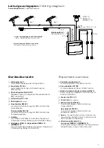
Installation information
Make sure your shipment is complete prior to commencing
installation. Please notify your supplier immediately in case of
any irregularities.
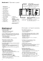
Connect all components only in accordance with the terminal
connection diagrams included with the central unit and the
drives.
You absolutely have to observe the regulations of the
professional association and state building regulations.
All wires except the feeder wire conduct 24 V DC and
must not be laid to gether with electric power lines (observe
VDE regulations or equivalent). The wiring type must always be
authorised by the responsible authority (fire service, technical
inspection, fire protection etc.). All maximum wire lengths and
mini mum cross sections must correspond with the technical
specifications provided in these instructions. Make sure to
observe the maximum possible connection options of the
control unit.
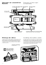
When positioning the central unit and the pushbuttons, please
follow all fire protection and state building regulations. Use
suitable mounting material. When installing the drives, please
pay attention to the occurring forces.
The installation of the RAZ K has to include a switch/circuit-
breaker in function of an isolating link. This must be located
near the unit and easy to reach for the user.
For the feeder wire use approved cables according to
DIN VDE 0250-xxx (or equivalent) with a cross-section of
max. 1,5 mm
2
, e.g. NYM-J 3 x 1,5.
Never wire the components of the same loop in a star configu-
ration. Always go from fire pushbutton to fire pushbutton, from
smoke detector to smoke detector and from drive to drive.
Make sure to connect shunt and terminating resistors for
central smoke and heat exhaust ventilation and alarm system
loops. Two monitoring diodes (1N 4007) must be installed in
the last conduit box in front of the drive and in accordance with
the terminal connection diagram.
Finish by checking all functions as well as function and operation
displays on the central smoke exhaust unit and the pivoting range
of the drives. Complete the assembler’s certificate included in
the control book and forward the request form and the corres-
ponding envelope to the operator of the central smoke exhaust
unit.
All drawings, installation and operating instructions and
the control book must be kept with the central unit.
Please store these documents in their entirety in the
central smoke exhaust unit for future reference.
Installationshinweise
Vor Beginn der Installation überprüfen Sie bitte die Vollständig-
keit der Lieferung. Bei Unstimmigkeiten informieren Sie um-
gehend den Lieferanten.
Anschluss aller Bauteile nur nach Anschlussplänen, welche der
Zentrale und den Antrieben beigefügt sind.
Beachten Sie zwingend die DIN, VDE sowie Vorschriften der
Berufsgenossenschaften und die Landesbauordnung (Auswahl
VDE 0100, VDE 0833, VDE 0800, BGV).
Alle Leitungen, außer der Netzzuleitung, führen 24 V DC.
Verlegen Sie diese nicht zusammen mit Starkstromleitungen
(VDE-Vorschriften beachten). Stimmen Sie den Leitungstyp
in jedem Fall mit der zuständigen Behörde (Feuerwehr, TÜV,
Brandschutzbehörde usw.) ab. Führen Sie die maximalen
Leitungslängen und minimalen Leitungsquerschnitte gemäß
der technischen Angaben in dieser Anleitung aus. Beachten
Sie die maximalen Anschlussmöglichkeiten der Zentrale.
Stimmen Sie die Platzierung der Zentrale und der Feuer-
taster ebenfalls mit der zuständigen Brandschutzbehörde ab
(Landesbauordnung beachten). Verwenden Sie geeignetes
Befestigungsmaterial. Bei der Montage der Antriebe beachten
Sie bitte die auftretenden Kräfte.
Die Installation der RAZ K muss als Trennvorrichtung einen
Schalter oder Leistungsschalter enthalten. Dieser muss in der
Nähe des Geräts und für den Benutzer leicht erreichbar sein.
Für den Netzanschluss verwenden Sie nur zugelassene
Leitungen nach DIN VDE 0250-xxx mit einem Leitungsquer-
schnitt von max. 1,5 mm
2
, z. B. NYM-J 3 x 1,5.
Gehen Sie bei der Leitungsverlegung nie sternförmig vor,
sondern immer von Feuertaster zu Feuertaster, Rauchmelder
zu Rauchmelder, Thermomelder zu Thermomelder und von
Antrieb zu Antrieb.
Beachten Sie die Anschaltung von Ersatz- oder Abschluss-
widerständen bei RWA- und Meldelinien.
In der letzten Abzweigdose vor dem Antrieb müssen zwei
Überwachungsdioden (1N 4007) gemäß Anschlussplan
installiert werden.
Überprüfen Sie zum Abschluss alle Funktionen, Funktions-
und Betriebsanzeigen der Rauchabzugszentrale sowie
den Schwenkbereich der Antriebe. Füllen Sie die Errichter-
bescheinigung im Kontrollbuch aus und leiten Sie das
Anforderungsformular sowie den dazugehörigen Brief umschlag
an den Betreiber der Rauchabzugszentrale weiter.
Zeichnungen, Montage- und Betriebsanleitung sowie
Kontrollbuch gehören in die Zentrale. Bitte legen Sie die
Unterlagen vollständig für den späteren Gebrauch in die
Zentrale zurück.
Merkmale
- Leitungsnetz ruhestromüberwacht (Linienüberwachung), 24 V
- Kabelzuführung von oben
- Kontrollanzeigen in der Zentrale für Alarm- und Linienüber-
wachung Netz/Akku, Antriebe, Feuertaster und Rauchmelder.
- Reset in der Zentrale möglich.
- Potentialfreier Kontakt für externe Alarm- und Störungs-
meldung sowie Anschlussmöglichkeiten von Lüftungstastern,
Zuluft-Antrieben und eines Wind-Regenmelders.
Achtung: Bei eingestellter Totmannschaltung (Aktivierung per
ConfigTool) werden sämt liche automatischen Lüftungssignale
(z.B. Wind-Regenmelder) nicht berücksichtigt!
- Bei Stromausfall während der Alarmöffnung bleibt der Befehl
“AUF” gespeichert, die Zentrale fährt weiter über Akku auf.
- Lüftungstaster im Alarmfall und bei jeglicher Störung gesperrt.
Bei Netzausfall blinkt die LED “Betrieb” in den Feuertastern.
- Die Rauchabzugszentrale RAZ K entspricht den geltenden
EN-Normen.
- Werkseitig voreingestellte Werte:
- Windmesszeit: 5 s
- Windimpulse pro Minute: 30
- Sperrzeit Wind/Regen: 50 s
- Lüftungszeit: 0 s, Lüftungszyklus: 0 h
(keine automatische Lüftung voreingestellt)
- Öffnungsweite: 1 s
(Automatikbetrieb, bei dem die Antriebe auch im Lüftungs-
betrieb voll öffnen und die Ausgänge nach Betätigung des
Lüftungstasters nach 3 Minuten stromlos geschaltet werden.)
Diese Werte können mit Hilfe des HAUTAU ConfigTool
geändert werden.
Features
- mains quiescent current-controlled (line monitoring),
system voltage 24 V DC
- cable feed from the top
- Indicator lights on the control unit for alarm and line monitoring
mains/battery packs, drives, fire pushbutton and smoke detector.
- Reset is possible in the control unit.
- Potential-free contact for external alarm and error messages
and connection options for ventilation pushbuttons, drives for
supply air, and a wind/rain sensor.
Attention: By setting deathman-version (activation by the
ConfigTool) every automatic ventilation signals (e.g. wind-rain-
sensor) are not considered!
-
In the event of a power failure during alarm opening, the
“OPEN” command remains saved, allowing the control unit to
open on battery power.
-
The ventilation pushbutton will be blocked in the event of an
alarm or any kind of failure. The “Mode” LED in the fire push-
buttons flashes in the event of mains failure.
- The RAZ K control unit corresponds to legal EN standards.
- Factory-preset values:
- Wind measurement time: 5 s
- Wind impulses per second: 30
- Locking time wind/rain: 50 s
- Ventilation time: 0 s, ventilation cycle: 0 h
(no automatic ventilation preset)
- Opening width: 1 s
(automatic mode, in which the drives open completely also in
ventilation mode and the outputs will be switched off the power
supply after 3 minutes after pushing the ventilation button).
These values can be modified with the HAUTAU ConfigTool.