


HAUTAU GmbH · Postfach 1151 · D 31689 Helpsen
Tel +495724/393-0 · Fax -125 · [email protected] · www.HAUTAU.de
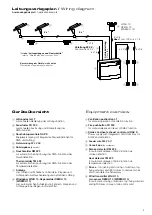
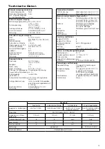
Power supply
Primary power supply
mains
Secondary power supply
battery pack
max. interrupt time
between power sources
< 1 ms
Primary power supply
Mains supply voltage
230 V AC / 50 Hz
(-10% / +10%)
System voltage
24 V DC (rated)
(18,0 V - 28,0 V)
Power consumption
170 W / Standby: 7,5 W
Terminal
screw-type terminal 2,5 mm²
Fuse
T 500 mA / 250 V
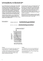
Secondary power supply
Battery pack
2 x 12 V / 2,6 Ah
Type of battery pack
lead, dim. 70 x 48 x 98 (mm)
Emergency power supply
72 h
Quiescent current in Standby < 16 mA
Current output after 72 h
4 A for 180 s acc. to
in emergency power supply DIN EN 12101-10
max. current output
4 A
Charging time
24 h
Terminal
flat plug 4,8 mm
Monitoring
yes, cyclic approx. every 300 s
Fuse
T 5,0 A / 250 V
Output drives
Voltage
24 V DC (rated)
(18,0 V - 28,0 V)
Ripple
< 5%
Current (rated)
4 A
Current (short-time)
5,8 A (for < 10 ms)
Opening-/Closing operation reversion of voltage polarity
Pulse off time during
reversion of polarity
approx. 2 s
Pulsing acc. to
yes, every 2 minutes
prEN12101-9
Automatic clearing
Open / Close in ventilation mode
after 3 min
Line monitoring
yes, until the last conduit box by
monitoring diodes with 3rd line
Terminal
screw-type terminal 2,5 mm²
Fuse
T 5,0 A / 250 V
Potential-free contacts
SHEV activation
changeover contact, max. 30 V / 1 A
Collective fault
changeover contact, max. 30 V / 1 A
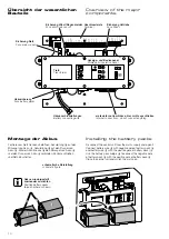
Material and mechanical characteristics
dim.; B x H x T (mm)
metal sheet housing 302x302x115;
PVC AP 287 x 236 x 112;
PVC UP 283x232x70 (112)
Housing
metal sheet for AP installation;
PVC (material) for AP und UP
installation
Colour
metal sheet: grey; PVC: white
Non-halogen yes
Silicone-free yes
RoHS compliant
yes
Connection and operation
applicable for SHEV
yes
applicable for ventilation yes
Ventilation function
no, ventilation blocked
in case of mains failure
Service
once a year
Change of battery packs every 4 years and in case of
fault function
Installation and environmental conditions
Nominal temperature
20 °C
Ambient temp. range
-5 °C to +40 °C
Installation situation
dry
applicable for
outdoor installation
no
Protection system
IP 30 (acc. to DIN EN 60529)
Approvals and certificates
Controlling equipment
certified by TÜV based on
prEN 12101-9
Power supply
certified by TÜV acc. to
EN 12101-10
CE compliant
yes, acc. to EMC Directive
2004/108/EG and Low-voltage
Directive 2006/95/EG
RoHS compliant
yes, acc. to Directive 2011/65/EG
Protection class
class I
Outputs
Fire pushbutton
automatic detectors
Ventilation pushbutton
Wind-/Rain sensor
applicable for models
HAUTAU FR 900 ..
RM 523 and TM 523
HAUTAU LT, LTA and
double rocker switch
HAUTAU WG/H,
REM/H and WREM/H
Voltage
24 V DC (rated) (19,3 V - 28,0 V)
Output, max. current load
120 mA
120 mA
120 mA
400 mA
Line monitoring
yes
yes
no
no
max. number
10
10
10
1
Emergency power supply
yes
yes
no
no
Fuse
electronic
T 400 mA / 250 V
Terminal
screw-type terminal 2,5 mm²
Technical specification