


15
Art. Nr.: 5090030031
Rev.: 00/2018-11-27
HSI 150-M... (HSI 90-M...) for smooth or corrugated cable ducts
with clip ring for connection to wall insert HSI 150 (HSI 90)
EN
Copyright © 2017 by
Hauff-Technik GmbH & Co. KG
Dept.: Technical Editing
Robert-Bosch-Straße 9
89568 Hermaringen, GERMANY
Tel.
+49 7322 1333-0
Fax
+49 7322 1333-999
Internet
www.hauff-technik.de
Reproduction of these installation instructions – even in ex-
tracts – in the form of reprint, photocopy, on electronic data
media or using any other method requires our written consent.
All rights reserved.
Subject to technical alterations at any time and without
prior announcement.
These installation instructions form part of the product.
Printed in the Federal Republic of Germany
1
Work stages
Reference numerals in drawings
1
►
Effect/result of a work step
For proper installation of the HSI 150-M...(HSI 90-M...) for
smooth or corrugated cable ducts, the following tools are
required in addition to the usual standard tools:
Tool set KES-M-W (Art. No.: 2128030000) consisting of:
– Torque spanner 4 to 20 Nm, 1/4 inch
– Extension 150 mm, 1/4 inch
– Socket for hex driver A/F 13, 1/4 inch
– Socket for hex driver A/F 8, 1/4 inch
1
Publishing notes
2
Explanation of symbols
3
Description (e.g. HSI 150-M168-WR)
4
Tools and aids required
5 Preparing for assembly
1
Heat the protective foil slightly and pull off completely.
2
If necessary, clean the spanner inserts in the black
closing cover by removing any residual concrete if
necessary.
Legend for: HSI150-M168-WR
1
Cable entry HSI150-K
2
System cover with union nut
3
Transition sleeve KES-M 150-M140
4
Ring clip
5
Corrugated pipe Ø 160 mm
6
Apply watertight closing to open end!
Contents
2
After this, tighten the clamping nut by turning it
to the right by hand or using the articulated face
spanner SLS 6G(D) so that it fits closely against the
wall insert (see Fig.: 5).
6
Assembly: System cover
1
Insert the pre-assembled system cover into the bayo
-
net of the wall insert by means of a light rotational
movement and ensure it is turned to the right as far
as it will go
(the red clamping nut may not yet be
tightened)
(see Fig.: 2).
►
When correctly mounted, the arrows on the
system cover match up with the arrows on the
square frame of the wall insert (see Fig.: 3 and 4).
3
Open the closing cover using the articulated face
spanner SLS 6G (accessory) or, if the perimeter insu
-
lation SLS 6G(D) (accessory) has been applied, using
the spanner inserts by means of movement to the
left (see Fig.: 1)..
1
Publishing notes ...............................................15
2
Explanation of symbols ....................................15
3
Description (e.g. HSI 150-M168-WR) ................15
4
Tools and aids required ....................................15
5
Preparing for assembly ....................................15
6
Assembly: System cover ...................................15
7
Assembly: Connection for smooth cable ducts
...........................................................................16
8
Assembly: Connection for corrugated cable ducts
(e.g. Fränkische Rohrwerke, other pipe manufac-
turers may vary) ................................................16
9
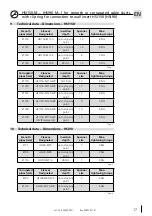
Technical data – Dimensions – HSI 150 ............17
10
Technical data – Dimensions – HSI 90 ..............17
11
Preparing installation of Hateflex hose systems
...........................................................................18
12
Pipe trench and support ...................................18
13
Installation, filling and compression ...............18
14
Bending radiuses ..............................................18
15a Installation in single rows ......................... 18
15b Installation in multiple rows ..................... 18
16
Assembly: ..........................................................18
17
Connection of Hateflex hose systems to shafts
and stations .......................................................19


