background image

48

3-90-07205R26_10/14

Harman PB105 Pellet Boiler

Label measures: 7.875" high X 6.5"wide

OMNI-Test Laboratories, Inc.

Report #/Rapport #135-S-16-6

Certified for U.S.A. and Cananda

Certifié pour les 

é

tats-Unis et le  Canada

BARCODE LABEL

008

Serial No.

N

o

 de série:

Harman PB-105

LISTED PELLET FUEL CENTRAL OR SUPPLEMENTARY FURNACES

FOR RESIDENTIAL USE

APPAREIL DE ChAUFFAgE CENTRAL OU SUPPLéMENTAIRE ENREgISTRé DE 

gRANULéS COMBUSTIBLES POUR USAgE DANS LES RéSIDENCES

Tested June 2006 to CSA-B366.1-M91, and UL 391-95
Install and use only in accordance with the manufacturer’s installation/operting 

instructions. Refer to authorities having jurisdiction for proper installation. Contact 

local building or fire officials about restrictions and installation inspection in your area. 

If there are no applicable local codes, follow ANSI/NFPA 211 and CAN/CSA B365. 

Special precaustions are required for passing the chimney through a a combustible 

wall or ceiling.
Inspect and clean exhaust venting system frequently in accordance with the 

manufacturer’s instructions. Use a 4” diameter type “L” or “PL” venting system.

Testé en June


2006 à CSA-B366.1-M91, and UL 391-95

Installez et utilisez en accord avec les instructions d’installation et d’opération du 

fabricant. Référez-vous à des professionnels avec autorité dans l’installation. 

Contactez le bureau de la construction.ou le bureau des incendies au sujet des 

restrictions et de l’inspection dans votre voisinage.
S’il n’y a pas de codes locaux, suivez alors ANSI/NFPA211 et CAN/CSA B365. 

Prenez des précautions spéciales lorsque vous faites passer une cheminée à travers 

un mur ou un plafond combustibles. Inspectez et nettoyez le sustème de ventilation 

fréquemment en accord avec les instructions du fabricant. Utilisez un système de 

ventilation de 4” de diamètre de type “L” ou “PL”.

Model

Modèle

Fuel

Combustible

Chimney Connector Size

Grandeur du Tuyau de Cheminée

BTUH/Kw Input Pellet

Rendement des Granulés BTUH/Kw

Electrical Rating

Classification 

électrique

Maximum Overcurrent Protection

Protection Maximum du Courant

Sidewall to Appliance
Backwall to Appliance
Combustibles to Pellet Vent
Stove Top to Ceiling
Alcove Height
Alcove Depth
Combustibles from Stove Front

Clearances to Combustibles/Espaces Libres aux Combustibles

20” (507 mm)

6” (152 mm)

3” (76 mm)

23.5” (596 mm)

66” (1673 mm)
80” (2032 mm)

36” (914 mm)

Mur Latéral à l’Appareil
Mur Arrière à l’Appareil
Matériaux Combustibles au Conduit de Fumée
Haut du Poêle au Plafond
Hauteur de l’Alcôve
Profondeur de l’Alcôve
Des Combustible au Devant du Poêle

(5) Spring Handles / (5) Poignées à Ressort
(1) 3/4” Boiler Drain / (1) Robionet de vidange 3/4”
(1) 3/4” Safety Relief Valve / (1) Soupape de Sécurité 3/4”
(1) 1/2” Aquastat Well / (1) Plomgeur de l’Aquastat 1/2”

(1) 1/2” Dual Temperature/Pressure Gauge / (1) Double Indicateur Température/Pression 1/2”

Essential parts and subassemblies provided for field assembly are as follows /

Pièces essentielles et sous-assemblée procurées pour l’assemblage sont les suivantes:

(1) 100’ Sensor Cable / (1) Câble de la Sonde 100’
(1) Outdoor Air Sensor / (1) Sonde Extérieure

(1) Flue Tunnel Weldment / (1) Ensemble Mécano-soudé de sortie des Gaz de Combustible

(1) Combustion Blower Assembly / (1) Ensamble Ventilateur de Combustion

(1) Heat Shield (Combustion Blower) / (1) Carter de Protection du Ventilateur de combustion

Date of Manufacture / Date de fabrication

2013   2014   2015   JAN   FEB   MAR   APR   MAY   JUN   JUL   AUG   SEP   OCT   NOV   DEC

Made in the U.S.A. / Fait aux 

é

tats-Unis

Do Not Remove or Cover This Label/Ne pas enlever ou recouvrir cet étiquette

Manufactured by/Fabriqué par: hearth & home Technologies, Inc.

352 Mountain house Road - halifax, PA 17032

DO NOT CONNECT THIS UNIT TO A CHIMNEY FLUE SERVING 

ANOTHER APPLIANCE

NE PAS CONNECTER CET APPAREIL à UN TUYAU 

DE CHEMINéE SERVANT UN AUTRE APPAREIL

WARNING!

DO NOT operate with fire chamber or ash removal doors open.

DO NOT store fuel or other combustible material within 

installation clearance area.

CAUTION!

 Hot while in operation.

DO  NOT  touch.  Keep  children,  clothing,  furniture  and  other  combustible 

material out of the installation clearance area.

Flooring must be a non-combustible material covering the installation 

clearance area, and 18” in front of, and 8” to either side of the fuel loading 

doors.

In the event of loss of electrical power:

Consult owner’s manual for restarting your furnace after power is restored.

ATTENTION!

Ne pas opérer si la porte du combustible ou la porte de la cuvette des 

cendres sont ouvertes. Ne pas placer le combustible et les matières 

combustibles à l’intérieur de l’espace désignée pour l’installation.

ATTENTION! 

 Chaud lors de l’opération.

NE  PAS  toucher.  Gardez  les  enfants,  les  vêtements,  les  meubles  et  les 

matériaux combustibles loin de l’espace désignée pour l’installation.
Le plancher de l’espace désigné pour l’installation doit ê fait de matière non-

combustible, de 18” en avant, et de 8” de chaque côté des portes d’entrée 

du combustible.

Dans le cas d’un manque d’électricité:

Consultez le manuel du propriétaire pour remettre la fournaise en marche 

lorsque l’electricité ést  revenue.

DANGER!

Risk  of  Fire  or  Explosion  -  Do  not  burn  garbage,  gasoline, 

naphtha, engine oil, or other inappropriate materials.

DANGER!

Risque  de  feu  ou  d’explosion.  Ne  pas  brûler  des  ordures,  de 

l’essence,  du  pétrole,  de  l’huile  moteur  ou  autres  matériaux 

inappropriés.

U.S. ENVIROMENTAL PROTECTION AgENCY

This model is exempt from EPA certification under 40 CFR 60.531

by definition [Wood heater (A) “air-to-fuel ratio”].

Rev D

P.N. 3-90-07206

PB-105

Pellet

Granulés

4”

113,900 BTUH (33.4 Kw)

120V, 4.45A, 60 Hz

20 AMP

Safety label

SAMP

le

 lAB

el

 ON

lY

Содержание PB 105

Страница 1: ...Keep clothing furniture draperies and other flammable materials away HOT SURFACES Glass and other surfaces are hot during operation AND cool down NOTICE Important operating and maintenance instructio...

Страница 2: ...Blower Combustion Blower Cover 3 4 FMPT Boiler Drain Access Cover to Secondary Ash Chamber Ash Door Viewing Glass Firebox Door Access Cover to Hopper Swing Plate Knob Control Board Cover Control Board...

Страница 3: ...ntrol 25 Outdoor Air Reset Operation 26 Control Board Operation 27 Automatic Ignition 28 29 Manual Ignition 30 31 Maintenance 32 Burnpot Maintenance 32 Burnpot Air Chamber 32 Ash Removal and Disposal...

Страница 4: ...damage bodily injury or even death SAVE THESE INSTRUCTIONS Hearth Home Technologies 352 Mountain House Road Halifax PA 17032 WARNING RISK OF FIRE Hearth Home Technologies disclaims any responsibility...

Страница 5: ...ew home construction warranty coverage begins on the date of first occupancy of the dwelling or six months after the sale of the product by an independent authorized HHT dealer distributor whichever o...

Страница 6: ...ONS This warranty does not cover the following Changes in surface finishes as a result of normal use As a heating appliance some changes in color of interior and exterior surface finishes may occur Th...

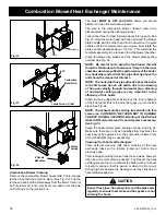
Страница 7: ...the ash chamber base Fasten the 4 nuts and lock washers provided to the studs by removing the access cover on the secondary ash chamber Step 2 Place the combustion motor onto the flue tunnel weldment...

Страница 8: ...ll be installed Things that need to be taken into consideration are the intended use of the boiler for example is the boiler going to be used as your primary heating system or is it going to be used a...

Страница 9: ...C 16 5 A 18 B 6 TOP VIEW F G 22 5 5 66 62 43 5 FRONT VIEW Notes A Manufacturer recommended minimum clearance B Minimum clearance to combustibles BUT NOT RECOMMENDED See Note C C Mfr s recommendation t...

Страница 10: ...an outside corner is 11 from center of pipe G The clearance to an inside corner is 12 H A vent must not be installed within 3 feet 90 cm above a gas meter regulator assembly when measured from the hor...

Страница 11: ...th Home Technologies strongly recommends the use of outside air in all pellet boiler installations especially those on lower level and main floor locations Per national building codes consideration mu...

Страница 12: ...only A combustion blower is used to extract the combustion gases from the firebox This creates a negative pressure in the firebox and a positive pressure in the venting system as shown in Fig 4 The lo...

Страница 13: ...occurred If creosote has accumulated it should be removed to reduce the risk of a chimney fire Guidance on minimizing creosote formation and the need for periodic creosote removal The chimney should...

Страница 14: ...is located on the face of the Feeder Cover It is pre cut except for several small tabs There is also a filler plate screwed to the inside to cover the top of the hole after the Outside Air Pipe has b...

Страница 15: ...oiler should never be powered by the use of an extension cord The recommended high and low voltages are 130 VAC 60 Hz maximum high voltage and 113 VAC 60 Hz minimum low voltage The furnace will contin...

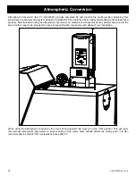
Страница 16: ...moisture and creosote it is strongly recommended that some form of temperature balance is incorporated into the return water system NOTICE When installing with the atmospheric conversion All of the p...

Страница 17: ...the operation of the solid fuel boiler 5 Have provision for preventing or adequate water capacity within the boiler to prevent damage to the boiler from loss of circulation due to electrical power fa...

Страница 18: ...SET TO DESIRED WATER TEMPERATURE NORMALLY NOT MORE THAN 120 DEGREES TEMPERED HOT WATER FOR SHOWERS AND FAUCETS Plumbing Installation COLD WATER SUPPLY MIXING VALVE SET TO DESIRED WATER TEMPERATURE NO...

Страница 19: ...BY THE INSTALLING CERTIFIED PLUMBER OR HVAC CONTRACTOR UNION SHUT OFF VALVE AQUASTAT WELL UNION SYSTEM SUPPLY 1 1 4 ITEMS SUPPLIED OPTIONAL PRESSURE REDUCING VALVE PRV OR COMBINATION PRV AND RELIEF V...

Страница 20: ...OMMENDED INSTALLATION INSTRUCTIONS FORTHE PROPER MOUNTING POSITION AND LOCATION WITHINTHE PIPING SYSTEM AIR VENT TYPICALLY INSTALLED INTHE HIGHEST ACCESSABLE LOCATION INTHE PIPING FROM ADDITIONAL ZONE...

Страница 21: ...build pressure to the point of opening the relief valve or with the atmospheric conversion it may allow the water to boil and exit through the over flow of the atmospheric tank Both scenarios may crea...

Страница 22: ...e from the wiring harness that connects to the feed motor Fig 1 Separate the black wires at the push on connectors for the feed motor Fig 2 Fig 3 The male connector will be on the wiring harness and t...

Страница 23: ...it may not be possible to get a low draft reading in this range In this case a maximum low draft of 55 is acceptable The adjustment screw is through the small hole to the right of the Igniter Light S...

Страница 24: ...hould be no more than 1 1 2 inches 38mm Pellet length can vary from lot to lot from the same manufacturer Tested and approved for use with wood pellets ONLY Burning of any other fuel will void your wa...

Страница 25: ...Lighting Mode Selector Switched betweenAuto and Manual lighting Mode Selector MIN TEMP Dial Used to turn the boiler on or off and set the desired minimum operating temperature of the boiler Status lig...

Страница 26: ...y 1 in temperature rise of the Outside Air Example 1 OAT Water Temp Degree Change Max set at 185 65 140 45 Min set at 140 60 145 40 55 150 35 50 155 30 45 160 25 40 165 20 35 170 15 30 175 10 25 180 5...

Страница 27: ...he secondary ash chamber area and also in the venting system which could cause damage in these areas NOTE If the system is run at the lower temperature settings conditions of the firebox boiler tubes...

Страница 28: ...into the feeder opening and then fill the hopper with pellets As the system works they will be burned 4 If Starting After an Empty Hopper Turn Feed Adjuster to TEST for one 60 second cycle This will f...

Страница 29: ...s cleaning that will be needed of the heat exchanger surfaces The cleaner these surfaces are kept the more efficient the boiler will be Store pellets in the manufacturer s wrapping until needed to pre...

Страница 30: ...will not be allowed to go out It will only be allowed to go to a minimum burn rate between the times the aquastat is calling for heat This rate is about 1 1 pound of fuel per hour If used in the Manua...

Страница 31: ...chimney vent pipe fire do the following 1 Call the fire department 2 Remove fuel from the burn pot using the burnpot scraping tool to scrape the pellets into the ash pan 3 Remove the ash pan from the...

Страница 32: ...y ash that has fallen through the holes during operation and cleaning Also at this time remove the feeder assembly cover and remove any fines that may have accumulated NOTE ALWAYS REMEMBER TO CLOSE TH...

Страница 33: ...st venting system The exhaust venting system should be inspected at least twice monthly to determine if cleaning is necessary Pay particular attention to screening in the vent cap The screen if presen...

Страница 34: ...rnpot opening At this time you can scrape and clean the burnpot and fines cleanout area 2 Open firebox door and vacuum ash from ledges and ash deflector You can also clean the firebox door viewing gla...

Страница 35: ...into the flue pipe See Fig 24 NOTE The exhaust probe sensing tip extends into this same area CARE MUST BE TAKEN NOT TO DAMAGE THE ESP DURING CLEANING Bending of the ESP will make it difficult to remov...

Страница 36: ...F VENT 1 Air fuel ratio is too rich a Feed rate too high b Draft too low caused by a gasket leak LOW HEAT OUTPUT 1 Feed rate too low 2 Draft too low because of gasket leak 3 Poor quality or damp pelle...

Страница 37: ...at when using the atmospheric conversion air bleeders and check valves may actually allow air into the lines Another reason it is important to have a licensed Plumber involved in each phase of your in...

Страница 38: ...installs in the side of the boiler and allows your domestic water to be heated by the heating system water Install the coil now by removing the round plate and replacing it with the coil and it s rou...

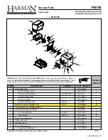
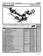
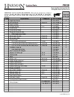
Страница 39: ...ch Retrofit Kit Pre 008341438 1 00 72212 Hopper Lid Assembly 1 10 72167A Hopper Lid Catch 2 00 72166B Hopper Lid Spring Latch Set of 2 1 00 00927 Y Rubber Grommet Hopper Lid 10 Ft 1 00 00248 Y 2 Contr...

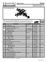
Страница 40: ...per Gasket 3 44 72206 8 5 Sheet Metal Bracket Qty 2 req 2 00 72203B 8 6 Ash Pan Assembly 1 10 72129 Y 8 7 Ash Door Assembly 1 10 72137A Y 8 8 Access Plate w Gasket 2 00 72132 Screw 1 4 20 x 3 4 Pkg of...

Страница 41: ...View Door Mounting Plate Gasket 10 Ft 1 00 88100 Y 14 Finished Body Weldment 1 89 07205W 15 Cleanout Rod Qty 3 Req 2 00 01036 Y Cleanout Rod Repair Kit 1 00 72210 Scraper Rod Guide Qty 3 Req 3 50 7218...

Страница 42: ...67900 Y 9MM Silicone Tube 5 Ft 1 00 511427 Y 28 4 Pellet Air Intake Assembly 1 10 06810A 28 5 Gasket Feeder Air Intake Pkg of 6 3 44 72224 6 Y 28 6 UL Feeder Air Intake 1 10 72222 28 7 Gasket Ultra Ai...

Страница 43: ...3 30 8009 25 Y 31 1 Spring Handle 500 Dia Pkg of 3 3 40 00086 3 3 Hardware Packages Nut 1 4 20 Zinc Plated Finished Hex Pkg of 100 3 30 8004 100 Y Nut 1 4 20 Zinc Plated Nylon Insert Lock Pkg of 100 3...

Страница 44: ...0 00957 Y Door Latch Kit Door Latch with Hardware 2 Sets 1 00 00036 Y 5 16 24 Grade 8 Yellow Zinc Finished Hex Nut Pkg of 50 3 30 8007 50 Y 5 16 24 x 3 4 Alloy Steel Black Oxide ButtonHeadCapScrew Pkg...

Страница 45: ...O D 4 12 I D BTU Input Range 0 and 9350 to 113 900 0 BTU if system is satisfied Min Burn 1 1 pound per hour Max Burn 13 4 pounds per hour 8500 BTU per pound figures Electrical 120 VAC 60 Hz Combustion...

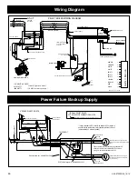
Страница 46: ...WATTS 200 WATTS 105 Series PELLET BOILER WHITE GREEN Relay enclosure box GRAINGER 1EGH7 RED RED WHITE G R E E N DPDT RELAY flange mtd GRAINGER 2XCO2 2 4 6 3 1 5 1 2 CONDUIT 8 7 16 3 AWG PVC CORD Thes...

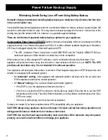
Страница 47: ...on blower only shut down Your appliance will pulse the blower every few seconds to clear exhaust until the fire is out NOTE The UPS provides safe shut down only It is not intended for continued operat...

Страница 48: ...1 2 Aquastat Well 1 Plomgeur de l Aquastat 1 2 1 1 2 Dual Temperature Pressure Gauge 1 Double Indicateur Temp rature Pression 1 2 Essential parts and subassemblies provided for field assembly are as f...

Страница 49: ...49 3 90 07205R26_10 14 Service Record Notes Date Of Service Description Of Service Performed By...

Страница 50: ...werful heating appliance boasts uncompromising attention to detail and helps preserve our planet by using environmentally responsible fuels Signature of Boxer Your premium quality hearth product desig...

Страница 51: ...3 90 07205R26_10 14...

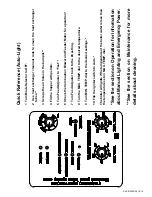
Страница 52: ...r and Feeder Motor for operation 7 Turn Feed Adjuster back to the 4 setting 8 Turn the MAX TEMP dial to the desired temperature 9 Turn MIN TEMP dial to the desired settings 10 Flip the igniter switch...

Отзывы: