Dry Seasoned Wood Only!
Oakleaf Woodburning Stove
Harman® • Oakleaf Owner's Manual_R23 • 2010 -___ • 09/15
23
3-90-798
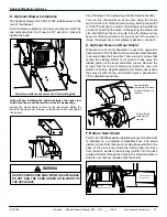
D. Optional Blower Installation
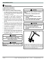
The optional blower kit #1-00-797032 installs easily to the
rear of the Oakleaf.
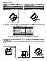
Hold the blower assembly into place and secure it with the
two bolts provided. You'll need a 3/8" wrench or socket to
tighten the bolts.
Notice: When installing the optional blower, the upper rear
shield must be moved upward to create the air passage.
Loosen the eight screws to remove the rear shield. Raise the
shield to the upper set of holes, re-install the shield, and tighten
the screws.
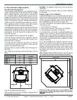
F. Bottom Heat Shield
Part #1-00-797058
must
be installed whenever the Oakleaf
is installed on a protected combustible floor. The shield
installs on four bolts that are protruding downward from the
base of the stove body. Slide the shield under the stove
from the back, as this is the only way it will fit. Lift into place
guiding the bolts through the holes in the shield and secure
with the nuts that are included with the shield.
Plug the blower into a properly grounded electrical outlet.
You can turn the blower on at any time using the rocker
switch on the rear of the blower housing. Setting the switch
to "AUTO" will keep the blower off until there is a significant
amount of heat from the stove. In this setting, the blower will
also shut off when the stove cools. Keep the blower on low
speed or off during low fires. As you get out of the low burn
range, the speed can be set wherever desired, or kept off.
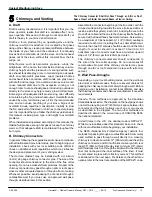
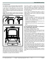
E. Optional Rear-vent Rear Shield
Whenever a rear vent configuration is used, the upper rear
heat shield, #1-00-797066 must be purchased and installed,
to accommodate the flue collar. There are eight screws that
secure the existing shield. You'll need to break away the
tabbed portion of the lower shield flue cut-out. Remove the
screws from the top-vent shield and install the rear vent
shield in it's place. Height adjustment for blower use is done
the same as with the top-vent shield in place. See Section
7D for detailed instructions.
ROUTE POWER CORD AWAY FROM THE APPLIANCE.
DO NOT RUN THE CORD UNDER OR IN FRONT OF
THE APPLIANCE.
WARNING
!
Use these Holes
Secure blower with one bolt on each end of the mounting plate.
Shown with lower
shield knockout
removed.
If not installing the
optional blower, the upper
knockout will need to be
removed.
Install nuts once shield is in place
Slide heat shield in from
the rear of the unit


