background image

From Program Mode (press the 

Program

button), you can enter setup mode by pressing either the “

CH 1

” button

or the “

CH 2

” button. Notice that when you do, several things happen on the screen:

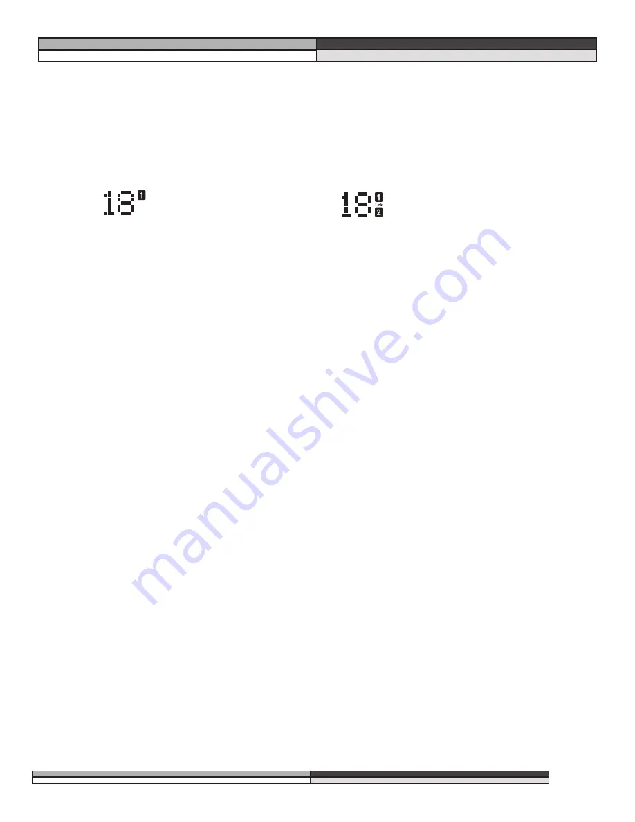
1. The reversed-text channel number (either “1” or “2”) to the right of the program number will light, indi-

cating the “active” channel. The other number will go out. (If you are working with a linked setup,
both the “1” and “2” will light, as well as the word “link” between the two numbers.)

2. The first line of text says. “Ch 1 Setup”. The second line of text indicates the setup’s title.

3. The third line of text shows the elements of the setup’s chain in their proper order.

4. The curve window shows text reading “FACTORY setup”, or “USER setup”.

5. Using the

Data Wheel

, scroll through the available setups. You should recognize these from the previ-

ous pages. The chain that is displayed in the window is the one that is active. All the DDP’s factory
setup names are listed in Appendix #1, page 24.

Viewing Elements of a Chain

Individual elements of every setup chain may be viewed and their parameters manipulated. We have provided
you with a full slate of parameters for each element. They are described in section 4. 

Linked Programs

Select a linked program. If you want to edit the parameters of a linked setup, simply press the
function button that corresponds to the element you want to edit. For example, if you wish to
edit the parameters of the compressor, just press the compressor button. It will light up, as will
the compressor icon to the right of the program number on the DDP’s display, indicating that you
are ready to edit the parameters of the compressor. As you do so, the STORE button will light
indicating that you have made changes to the parameters and must store them in order for them
to be saved for later use.

Dual-Mono Programs

Using a dual mono program number, (one without the “LINK” icon lit between the “CH1” and
“CH2” icons) select the element you wish to edit by simply pressing the corresponding function
button, like the 

Compressor

button, for example. Note that as you do, the icon corresponding to

the element lights up beside the program number, the function button lights up, and the top line
of text shows the element being edited. Also note that either the CH1 or CH2 icon is lit. It lets
you know which channel’s compressor you are editing, for example. To edit the other channel’s
compressor, simply press the 

Compressor

button again. Everything stays the same except for the

CH1 icon has turned off and the CH2 is lit. You can switch between channels in this way from
any chain element. If the CH1 and CH2 setups are different from each other, trying to switch to
an element not present in the other setup will result in nothing happening at all. You will remain
in the channel that contains the element you selected. 

,,,,,

yyyyy

zzzz

{{{{{

||||

DDP

Digital Dynamics Processor

,,,,

yyyy

zzzz

13

Section 3: Setup / Basic Operation

Setup mode in
dual mono

Setup mode in
linked mode

Содержание dbx DDP

Страница 1: ... DDP Digital Dynamics Processor Operator Manual ...

Страница 2: ...nit or in the system to which it is connected can result in full line voltage between chassis and earth ground Severe injury or death can then result if the chassis and earth ground are touched simultaneously LIVE E NEUTRAL EARTH GND CONDUCTOR L N BROWN BLUE GREEN YEL BLACK Normal Alt WIRE COLOR WHITE GREEN U K MAINS PLUG WARNING A moulded mains plug that has been cut off from the cord is unsafe D...

Страница 3: ...e Essers 18 Editing the Sidechain EQ 18 More About Sidechain EQ 19 Changing Chain Types 20 Saving Programs and Setups 20 Saving a Program 20 Saving a Setup 21 Replace Old 21 Store New 21 Section 5 Utility Functions 23 Contrast 23 Sample Rate 23 AutoLoad 23 Digital Input Mode 23 Digital Output Mode 24 Digital Input Level Controls 24 MIDI 24 SysEx 24 A D Calibration 24 Section 6 Appendices 25 APPEND...

Страница 4: ...way 1 Make sure that AC power is not connected to the DDP Turn off the power to your console recorder and other devices in your setup 2 Make audio connections in one of several ways A Wire the analog inputs and outputs into a patch bay This method will prove to be the most useful in the long run B Connect the DDP s inputs and outputs directly to the insert point of a console s input strip group ou...

Страница 5: ...DI In and Out Thru Connectors These connectors provide full MIDI functionality to the DDP The Out Thru jack allows you to use the DDP at any point in the MIDI chain All automation functions are accessed through the MIDI connectors Analog Inputs and Outputs Each analog channel features both XLR and 1 4 TRS electronically balanced inputs and outputs They may be used in a balanced or unbalanced confi...

Страница 6: ...trol digital input analog output digital input meter gain reduction meter A D Convertor D A Convertor Dynamics Processor digital output meter digital output analog output meter analog output control DSP Software based Operations Bypass Figure 1 DDP Signal Flow Parameter measurement units Digital conversion indicator Gain Reduction meter 3 parameters per page Parameter page number Program number Ch...

Страница 7: ...Mono Programs Figure 3 Program Components Gate The gate is a dbx expander gate which gives control over the ramp or ratio of the opening There are also Attack Hold and Release times available Transient Capture Mode is also found in the Gate section with variable delay times available For a complete list of the parameters available in the gate see sec tion 4 For an explanation of Transient Capture ...

Страница 8: ...cs processing tasks on digital signals without having to leave the digital domain The DDP Digital I O also offers the ability to convert analog to digital signals using the proprietary dbx TYPE IV Conversion System The dbx TYPE IV algorithms capture an analog signal into the digital domain while maintaining the best qualities of an analog recording and minimizing the sometimes harsh qualities of d...

Страница 9: ...ing up a proper compression curve is the curve win dow In the curve window you can see the combined effects of all compression related parameters expressed in a graphical format The figure below shows the different parts of the curve window you will see as you edit the gate compressor and limiter functions of the DDP When working with the sidechain EQ or the in line EQ the curve window changes to ...

Страница 10: ...h is set in the limiter section the signal is not being processed by the limiter section If the DDP s screen shows that you are getting gain reduction it is through some other chain element To determine which element is triggering gain reduction look at the other threshold meters to determine which ele ment s threshold is being exceeded by the signal When the signal exceeds the threshold set in th...

Страница 11: ... the display indicates the program number It is the method used to bookmark programs and all programs have a program number Each program can store either a linked setup or two dual mono setups There are two ways to take a look at the setup for any program 1 While in program mode the display will show the chain for each setup in the curve window located on the far right side of the display The abbr...

Страница 12: ...ection 5 for more information on AutoLoad and other utility features In AutoLoad mode it s best to scroll through programs while in Bypass mode Enter Bypass mode by pressing the Bypass button Its LED will light indicating that the DDP is in Bypass mode The Bypass Button The Bypass button on the DDP works like an analog processor in order to give you more visual feedback When you engage the bypass ...

Страница 13: ... zzzz DDP Digital Dynamics Processor yyyy zzzz 11 Section 3 Setup Basic Operation LINKED chains The following chain types are available in any Linked Setups Chain Type 1 What the DDP screen shows The chain that makes up the setup EQ G C DS L Equalizer Gate Compressor De Esser Limiter Limiter Chain Type 2 What the DDP screen shows The chain that makes up the setup SEQ G C DS L De Esser Equalizer Ga...

Страница 14: ...Type 3 What the DDP screen shows The chain that makes up the setup EQ C DS L Equalizer Compressor De Esser Limiter Chain Type 5 What the DDP screen shows The chain that makes up the setup SEQ G C DS De Esser Chain Type 4 What the DDP screen shows The chain that makes up the setup SEQ G C L Equalizer Gate Compressor Limiter Chain Type 6 What the DDP screen shows The chain that makes up the setup SE...

Страница 15: ... you wish to edit the parameters of the compressor just press the compressor button It will light up as will the compressor icon to the right of the program number on the DDP s display indicating that you are ready to edit the parameters of the compressor As you do so the STORE button will light indicating that you have made changes to the parameters and must store them in order for them to be sav...

Страница 16: ...ent must first be in the on position EDITING GATES Parameters of the Gate The parameters included on the DDP for gating operations are as follows Off on This is a bypass for the gate section Turning it to off deactivates the minus section of the threshold meter and the plus sign is darkened indicating that the gate is passing signal through regardless of the other gate settings Threshold range fro...

Страница 17: ...eact to the signal For a complete explanation of TCM Transient Capture Mode see section 6 EDITING COMPRESSORS Parameters of the Compressor The parameters included on the DDP for compression operations are as follows Off on As with the gate the compressor section must be turned on The curve window will show the compres sion threshold as well as the ratio and gain levels dbx OverEasy off knees 1 10 ...

Страница 18: ...B to 20dB When a signal is compressed by definition some of its gain is taken away It there fore becomes necessary to boost the now compressed signal back up to a useable level As you make this adjust ment you can see the effect in the curve window The compressed signal is now more dynamically controlled and can be boosted to a level that was not possible before it was compressed Attack control fr...

Страница 19: ...eshold this can be disconcerting given the fact that it appears that much more signal actually gets through the threshold Also it is possible to set the threshold of the limiter below the threshold of the compressor causing all of the gain reduction to happen in the limiter and none to happen in the compressor As you do this you will notice that the curve window displays exactly what the threshold...

Страница 20: ...meters of the EQ The parameters included on the DDP for EQ operations are as follows Off on Like any other element the EQ must be turned on Monitor off on If you are using a program number that has the sidechain functionality enabled the next para meter you see will be MONITOR The sidechain monitor lets you hear the signal you are using in the sidechain path as opposed to the signal you are using ...

Страница 21: ...ing the recording of cymbals and tom toms a compressor with an equalizer in the sidechain path can help prevent tape saturation The equalizer can be adjusted for boost with a peak of about 5kHz causing the cymbal to be compressed on a very loud crash stopping tape saturation at high frequencies where there is less head room However gentle tapping of a drumstick or brushing of the cymbal will not b...

Страница 22: ...will need to store the new program you have created You may save your work at any time If you like to live dangerously just save before you finish the session or save more often it s up to you The store LED will light as you scroll to new chains indicating that you must press store in order to make the current selection active in the program you are in After you have pressed store press program ag...

Страница 23: ... you have been editing a dual mono program If you have been working with a linked program your second choice will be Link Setup Make your selection by pressing the Store button again Remember that there is room in the DDP to store 100 linked setups and 100 mono setups in addition to the factory setups 2 Like above you are asked to name your setup Again there are instructions for you in the curve w...

Страница 24: ...ps already in the library scrolling by on text lines 1 and 3 parameter 1 and parameter 3 This indicates that you are placing your new setup between the two setups displayed above and below your new one The DDP makes room for your setup no matter where you want to place it 3 Pressing Store once more saves the setup in the spot you chose and after a brief pause the screen display the Done line and y...

Страница 25: ...is used in a live sound situation the ramifications could be disastrous if someone bumped the data wheel while signal was being passed through the DDP With AutoLoad in the OFF position you can scroll to other program numbers without affecting the sound being passed through the DDP As you make changes to a program then move the data wheel to another program number the Load button will flash telling...

Страница 26: ...ps and output configurations These are the SysEx channels SysEx control is twofold SysEx channels range from 0 16 and OMNI Other MIDI features follow on utility pages 3 through 7 Page 3 of the Utility menu allows you to set the MIDI and SysEx channels for the DDP Page 4 allows you to perform MIDI merging CCs are another good and easy way of communicating with the DDP For a complete guide to the fu...

Страница 27: ...e TYPE IV process takes over as the means of converting the analog signal to a digital signal This means that you may hit 6dB on the digital input meters for the DDP and not hear any audible distortion This behavior is not unlike an analog tape machine In conjunction with TSE Tape Saturation Emulation the essence of the analog signal is captured to the digital medium in a way that preserves the co...

Страница 28: ...hasing errors it is enough to give the device time to start to react before the signal arrives at the point of processing The controls for the TCM section are in the Gate parameter area While the effect is global the gate must be turned on in order for the TCM module to work If you want to use the TCM functions without the gate simply turn the gate on and set the ratio to 1 1 and the threshold to ...

Страница 29: ...ession with heavy sweetening Telephone EQ G C DS L Medium compression with heavy EQ Phat EQ G C DS L Light compression with extra bass Mr Master EQ G C DS L Light overeasy compression with just the right EQ for your DAT Catz Meow EQ G C DS L So light you will not even know it is on SCh Bass EQ G C DS L External sidechain for your bass Thiknchunky SEQ G C DS L Medium compression in the middle St Dr...

Страница 30: ...dechain EQ with light compression to enhance the low mids and a fair amount of gat ing Slap Bass EQ G Cmp L EQ with heavy compression and a lot of gating Rumble Bass EQ Cmp DS L Light overeasy compression with the top rolled out Martin s Gt EQ G Cmp L Mild compression with a little EQ for your prized acoustic guitar F Pick AcGt EQ G Cmp L Medium Compression with a little gating and EQ to keep your...

Страница 31: ...8 SYNTH BATH St Synth linked 19 TICKLE YOU Tickle Me linked 20 DREAMING Light Mix linked 21 IS IT ON Catz Meow linked 22 A CAPPELLA St Vocal linked 23 LINKED DEF 1 St Def 1 linked 24 LINKED DEF 2 St Def 2 linked 25 LINKED DEF 3 Ext Sch Def linked 26 NASHVILLE Country Voc Clear Voc 27 LA VOCALS Tight Voc Ambient Voc 28 INDIE VOC Small Voc De ess Voc 29 KARATE Solid Kick Swift Kick 30 TOM BOY Ringin...

Страница 32: ... 20 chain1 Comp Ratio cc 21 chain2 Comp Ratio cc 22 chain1 Comp db gain cc 23 chain2 Comp db gain cc 24 chain1 Comp Knee Switch cc 25 chain2 Comp Knee Switch cc 26 chain1 Comp Auto Mode cc 27 chain2 Comp Auto Mode cc 28 chain1 Comp Attack cc 29 chain2 Comp Attack cc 30 chain1 Comp Hold Time cc 31 chain2 Comp Hold Time cc 32 chain1 Comp Release cc 33 chain2 Comp Release cc 36 chain1 Limiter On Off ...

Страница 33: ...ysEx implementation dd n 2 denotes the 1st through 7th bits of the nth byte and dd n 1 denotes th 8th bit of the nth byte Note All data that is requested or received is in split byte format unless noted otherwise F7 h System Exclusive End Message byte Procedures In the following section SYS_HEAD refers to a valid System Exclusive header The System Exclusive header starts with the System Exclusive ...

Страница 34: ...h dd 1st 1 dd 1st 2 dd nth 1 dd nth 2 F7 h dd n Bulk Dump Data The Receive Bulk Dump procedure is used to load all User Programs into the DDP A software version number is imbedded in the data Receive Key Scan Code 54h SYS_HEAD 54 h cc F7 h cc Code for the Key Scan note there is only one byte not two The Receive Key Scan Code procedure is used to emulate a button press on the front panel of the DDP...

Страница 35: ...e but is ignored if received by the DDP Reset Program 20h SYS_HEAD 20 h F7 h The Reset Program procedure causes the DDP to reload the current saved program Reset Device 21h SYS_HEAD 21 h F7 h The Reset Device procedure causes the DDP to reboot the software as if the power had been turned off and then back on If edits have been made to the current program without saving they will be lost yyyyy zzzz...

Страница 36: ... Hi Bytes 00 0A 00 06 12 Character Setup Name dynamic 00 31 00 3A 00 52 00 76 00 62 00 20 00 32 00 3A 00 47 00 74 00 52 00 76 Null to indicate end of Character String 00 00 Misc Setup Data too dynamic to document 00 07 00 00 00 06 00 00 00 03 00 06 00 03 00 32 00 08 00 03 00 00 00 00 00 02 00 04 00 00 00 00 00 02 00 08 00 00 00 00 01 7E 00 00 00 00 00 20 01 7F 00 00 00 00 00 20 00 00 00 00 00 00 0...

Страница 37: ...id not collect Do not ship parcel post This warranty is valid only for the original purchaser and only in the United States 1 The warranty registration card that accompanies this product must be mailed within 30 days after purchase date to validate this warranty Proof of purchase is considered to be the burden of the consumer 2 dbx warrants this product when bought and used solely within the U S t...

Страница 38: ...dB with transient material A weighted 22 kHz bandwidth Up to 120 dB with transient material unweighted 22 kHz bandwidth Typically 114 dB with program material A weighted 22 kHz bandwidth Typically 112 dB with program material unweighted 22 kHz bandwidth THD Noise 0 002 typical at 4 dBu 1 kHz input gain at 0 dB Frequency Response 20 Hz to 20 kHz 0 0 5 dB Interchannel Crosstalk 85 dB at 1 kHz input ...

Страница 39: ...segment lightpipe bar graph at 24 18 12 6 0 6 12 and 18 dBu I O Meter Switches Green lightpipe switch for each channel indicates input level is selected Options Digital I O Card AES EBU XLR and S PDIF RCA in and out software selectable format Power Supply Operating Voltage 100 VAC 50 60 Hz 120 VAC 60 Hz 230 VAC 50 60 Hz Power Consumption 22 Watts Mains Connection IEC 320 receptacle Backup Battery ...

Страница 40: ... Utah 84070 Phone 801 568 7660 Fax 801 568 7662 Int l Fax 219 462 4596 Questions or comments E mail us at customer dbxpro com or visit our World Wide Web home page at www dbxpro com A Harman International Company 18 2211 A 3 31 98 ...

Отзывы: