page 29
DriveCore Install DA Series Operation Manual
Editing DSP Settings
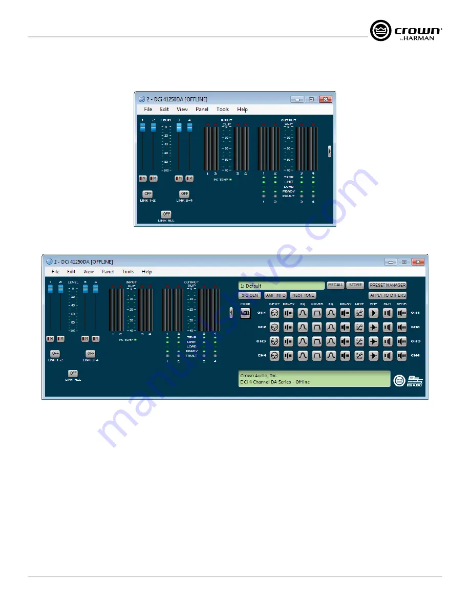
Configuration Panel
The Configuration panel can be accessed by clicking the amplifier icon from the Room window in Audio Architect. It provides access to all the amplifier's settings to
configure and optimize the amplifier for the loudspeaker system. When viewing the Configuration panel, the panel can be expanded or minimized using the
Arrow
button
(shown on the right side of the Basic Configuration panel in
Figure 36:
Basic Configuration panel
Figure 37:
Advanced Configuration panel
Level Faders
Use these faders to adjust the signal level for each channel.
Mute Buttons
Use these buttons to mute each channel.
Link Buttons
These buttons can be used to link the controls of channels for ganged operation.
Input Signal Level Meter
The measurement range of these input meters is from 0 dBFS to -40 dBFS, with 0.5 dB resolution. Each audio channel has the following monitors:
• Switched audio input (this meter shows only the switched (selected) audio input post the Input Audio Router)
• Clip indicator
• Peak + rms levels
Output Signal Level Meter
The measurement range of these output meters is from 0 dB to –40 dB, with 0.5 dB resolution. The monitors are scaled so that 0 dB is referenced to the full rated output
voltage of the amplifier. The wider left meter is rms and the right meter is peak for each channel. An output clip indicator is also provided.


