Harman Kardon DPR 1001 Скачать руководство пользователя страница 36

your system, changing devices or other common
tasks. Thanks to the remote’s two-line display, it is
easier than ever for you to take advantage of the
power of macro commands.

Recording a Macro

To record a macro into the remote’s memory, follow
these steps:

1. Press and hold the 

Program Button

y

for

about three seconds while the message shown 
in Figure 15 appears in the 

LCD Information

Display

2

. Release the button when the red

light under the 

Set Button

F

appears.

2. The 

MAIN MENU

message (Figure 16), will

appear in the LCD display and the 

Set Button

F

will remain illuminated in red. Press the 

Navigation Button

D

three times so that

MACRO

appears on the bottom line of the LCD

screen, as shown in Figure 37. Press the 

Set

Button

F

to enter the main macro menu.

Figure 37

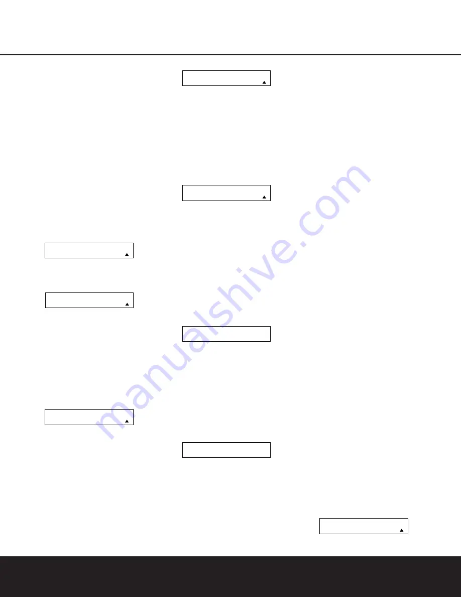
3. At the next menu screen (Figure 38) press the 

Set Button

F

to begin recording a macro.

Figure 38

4. The next display screen (Figure 39) is where you

select the button that will be used to recall the
macro. The choices are the 

Power On Button

1

or one of the discrete 

Macro Buttons

.

Press the 

/

¤

Navigation Buttons

n

until

the name of the button you wish to program the
macro into is shown and press the 

Set Button

F

. For this example we will show how to 

program a series of commands that will be 
sent when the Power button is pressed.

Figure 39

5. The next screen that appears (Figure 40) is where

you select the device for the first command that
will be sent out as part of the macro. Press the

/

¤

Navigation Buttons

n

until the name

of the device appears in the lower line in the LCD
display. For this example, the first button we want
to have the macro “press” is the Power On but-
ton, so the AVR device is selected. Press the 

Set

Button

F

when the desired device name

appears to move to the next programming step.

Figure 40

6. The next display (Figure 41) is where you begin

entering the individual commands for the macro,
in the order you wish them to be transmitted.
Remember that when you want to change devices,
you must first press the 

Input Selector

de

for that button, and then press the Command or
Function key. Since we want to program a series
of events that occur each time the Power On 
button is pressed, press the AVR button. In your
specific macro, this is the first command button.

Figure 41

7. The next display (Figure 42) and the subsequent

screens are where the actual macro programming
take place. The words at the left side of the top
line of the display show the button that is being
programmed (e.g., the 

Power On Button

1

or

one of the 

Macro Buttons 

) and the indica-

tion at the right side of the top line shows the
number of macro steps available of 20 possible
steps. Following the instructions on the remote’s
LCD screen, press the first key you wish to be
transmitted in the macro. In our example, we first
want the DPR to turn on, so the 

Power Button

1

should be pressed.

Figure 42

8. Once the first command button for the macro has

been pressed, continue to press the buttons you
wish to be part of the macro, in the order they will
be used. Press each button within five seconds of
the last button, remembering to press the 

Input

Selector

34

when you are changing device

functions. As the buttons on the remote are
pressed, the remote’s display screen will show the
steps in the macro as they are programmed
(Figure 43).

Figure 43

9. For our example, we first want the AVR Power On

button pressed, followed by the TV Power On, fol-
lowed by the Cable Box On, followed by the
selection of the Logic 7 mode. To do that, press
the buttons in this order:

• 

Power On

1

• 

VID 2/TV

3

• 

Power On

1

• 

VID 3/Cable

3

• 

Power On

1

• 

AVR

4

• 

Logic 7

7

As each button is pressed to enter it into the
macro you will see the button names appear and
then scroll up on the LCD display as your confir-
mation of the key entry (Figure 43).

10. When all commands for the macro have been

entered, press the 

Set Button

F

to save the

macro. The display screen will show the button 
to which the macro has been programmed and
the number of steps used, and the word 

SAVED

will blink four times in the lower line of the LCD 
display. When the display returns to normal, the
macro has been entered and the remote is ready
for operation.

11. If a macro has been programmed into the 

Power

On Button

1

, it will play back anytime the

Power On button is pressed. As the macro plays,
you will see the steps appear in the remote’s LCD
display. Macros programmed into one of the four
discrete Macro buttons may be activated at any
time by pressing the appropriate button.

Erasing a Macro

Once a macro has been created and stored in the
DPR remote’s memory, you have the option of erasing
it. You may do this at any time by following these
steps:

1. Press and hold the 

Program Button

O

for

about three seconds while the message shown 
in Figure 15 appears in the remote’s 

LCD

Information Display

2

. Release the button

when the red light under the 

Set Button

F

appears.

2. The remote’s 

MAIN MENU

message (Figure

16), will appear in the LCD display and the 

Set

Button

F

will remain illuminated in red. Press

the 

Navigation Button

D

three times so

that 

MACRO

appears on the bottom line of the

LCD screen, as shown in Figure 37. Press the

Set Button

F

to enter the main macro menu

branch.

3. At the next menu screen (Figure 44) press 

/

¤

Navigation Buttons

n

until the bottom line in

the remote’s LCD display reads 

ERASE A

MACRO

, as shown in Figure 44. Press the 

Set

Button

F

to begin the process of erasing a

macro.

Figure 44

M A C R O

E R A S E   A   M A C R O

[ A V R ]

[ A V R ]   P O W E R   O N

P O W E R   O N         0 0 / 2 0

S E L E C T   K E Y   P R E S S

S E L E C T   A   D E V I C E

A V R

S E L E C T   A   D E V I C E

A V R

R E C O R D   A   M A C R O

P O W E R   O N

M A C R O

R E C O R D   A   M A C R O

M A I N   M E N U

M A C R O

36

CONFIGURING THE REMOTE

CONFIGURING THE REMOTE

Содержание DPR 1001

Страница 1: ...DPR 1001 Digital Path Receiver Owner s Manual Power for the Digital Revolution...

Страница 2: ...Functions 13 Zone II Remote Control Functions 14 Installation and Connections 16 System Configuration 16 Speaker Placement 17 Speaker Optimizer 18 Input Setup 18 Surround Setup 19 Speaker Setup 21 De...

Страница 3: ...scan DVD players the DPR 1001 also features high bandwidth low crosstalk component video switching Coax and optical digital outputs are available for direct connection to digital recorders and both t...

Страница 4: ...e top of the unit or place objects directly over them There is the remote possibility that the rubber padding on the bottom of the unit s feet may leave marks on certain wood or veneer materials Use c...

Страница 5: ...ct Button 3 to scroll through the available choices until the desired mode appears in the Main Information Display F For more information see page 26 4 AM FM Selector Pressing this button will auto ma...

Страница 6: ...he unit from the silenced condition E System Configuration Indicators One of these indicators will light after the Set Button has been pressed to indicate which configuration option is in use Press th...

Страница 7: ...the number of channels available from the input source The left center right surround and surround back speaker indicators are composed of overlapping ovals while the subwoofer is represented by a sin...

Страница 8: ...s to the PLAY OUT audio jacks on a VCR or other video source a b c d e f g i i j 31 32 36 h k 34 37 38 33 35 550W SWITCHED 50W 0 5A MAX SPEAKERS 8 LFE SUB FR FL LFE SUB FR FL FM Antenna AM Antenna Mul...

Страница 9: ...should be connected to the red terminal on the Front Right speaker with the older color coding Connect the black terminal on the receiver to the matching black negative terminals for each front speake...

Страница 10: ...und Mode Select Button 6 8 Channel Input Select SPL Select Button EzSet Microphone Sensor Lens NOTES The function names shown here are each button s feature when used with the DPR 1001 Most buttons ha...

Страница 11: ...ak will change to monaural reception See page 28 for more information m Channel Select Button This button is used to start the process of setting the DPR 1001 s output levels to an external source Onc...

Страница 12: ...Delay Select Press this button to begin the process for setting the delay times used by the DPR 1001 when processing surround sound After pressing this button the delay times are entered by pressing t...

Страница 13: ...d in the room where the DPR 1001 is located press this button to raise or lower the volume in that room When it is used in a remote room with a sensor that is con nected to the Multiroom IR Jack this...

Страница 14: ...ocal building codes in your area When connecting wires to the speakers be certain to observe proper polarity Note that the positive terminal of each speaker connection now carries a specific color cod...

Страница 15: ...e obstruction may prevent the remote sensor from receiving commands In this event an optional remote infrared IR sensor may be used Connect the output of the remote sensor to the Remote IR Input Jack...

Страница 16: ...ers are seated in the desired area Rear surround speakers are required when a full 7 1 channel system is installed and they may also be used as an alternative mounting position in a 5 1 channel sys te...

Страница 17: ...king this adjustment you will need to find the impedance specification for your speakers This informa tion is often found on a label attached to the speaker and it is usually shown in the owner s manu...

Страница 18: ...gital or DTS may not be changed Selection of the front panel jacks as an output will remain effective as long as the DPR 1001 is on Once the unit is turned off the jacks will revert to their normal us...

Страница 19: ...Dolby Digital or DTS Digital soundtracks are in use See page 26 for a complete explanation of the Logic 7 Surround modes On the DSP menu the choices are the DSP surround modes designed for use with tw...

Страница 20: ...rround channel When LARGE is selected a full range output will be sent to the surround channel outputs and NO surround channel signals will be sent to the subwoofer output When NONE is selected surrou...

Страница 21: ...hen the Set Button p to return to the MAIN menu Delay Settings If Dolby Digital Dolby Pro Logic or DTS is selected as the surround mode for an input you may need to adjust the delay time setting The d...

Страница 22: ...ured for their large or small settings as outlined above and turn off the OSD system if it is in use 2 Adjust the volume so that it is at 15dB as shown in the on screen display or Lower Display Line B...

Страница 23: ...r The right corner of the bottom line of the remote s display will show the output level of the speakers as the test tone circulates The level will show as a direct SPL indication between 66dB and 79d...

Страница 24: ...of which device such as the DVD or another video source is in use The factory setting for the remote is to have the Transport Forward Reverse Play Buttons G Transport Fast Play Scan Forward Reverse Bu...

Страница 25: ...present in all stereo recordings However for stereo but not surround programs we suggest that you experiment with the other modes Surround modes may be selected using either the front panel controls...

Страница 26: ...ther decoding techniques The Logic 7 M or Music mode should be used with analog or PCM stereo sources Logic 7 M enhances the listening experience by presenting a wider front soundstage and greater rea...

Страница 27: ...tream Indicator A will light to show which type of signal is playing DOLBY D When the DOLBY D indicator lights a Dolby Digital bitstream is being received Depending on the settings on the source playe...

Страница 28: ...ired frequency band is selected 3 Press the Tuning Mode Selector 7l to select manual or automatic tuning 4 To select stations press the Tuning Selector 8 w When the Auto Tuning mode is in use press an...

Страница 29: ...to CHANNEL in the System Configuration Indicators Within five seconds press the Set Button again and the on screen display and the Lower Display Line B will change to FRONT L LEVEL indicating that th...

Страница 30: ...e the default condition so that the same volume level is always used at turn on you will need to make an adjustment in the ADVANCED menu To start the adjustment press the OSD Button to bring the MAIN...

Страница 31: ...ress the Navigation Button n until the MULTI ROOM line is highlighted Press the Set Button p to enter the MULTI ROOM menu Figure 14 Figure 14 When the MULTI ROOM menu appears the MULTI ROOM line will...

Страница 32: ...her brand devices may be programmed into the DPR 1001 remote using its extensive library of remote codes or a head to head learning process for codes not in the internal library Thanks to the remote s...

Страница 33: ...rogram the remote manually To automatically search through the codes that are available for a specific device type e g DVD VCR follow these steps 1 Turn on the power to the device you wish to program...

Страница 34: ...device categories and press the Set Button p when the device for which you wish to set the codes appears For this example we will select TV to enter the codes needed to operate your TV 4 The next men...

Страница 35: ...s used to control a VCR Press the Set Button F when the desired device combination appears Figure 36 5 Once the new device is selected the remainder of the process will select the codes for the specif...

Страница 36: ...mple we first want the DPR to turn on so the Power Button 1 should be pressed Figure 42 8 Once the first command button for the macro has been pressed continue to press the buttons you wish to be part...

Страница 37: ...nds for the video device Punch through enables you to easily program the remote to do this Volume Punch Through Follow these steps to enable the Volume Up Down and Mute controls from one device to be...

Страница 38: ...pressed while the master device is in use Returning the Channel Control Settings to Default Operation If you wish to remove the Channel Punch Through so that the commands for Channel Up Down are retur...

Страница 39: ...ton F again to immediately use the EzSet feature to calibrate the system as shown on pages 22 and 23 Renaming While the names given to the buttons and inputs on the DPR represent recognizable categori...

Страница 40: ...main illuminated in red Press the Navigation Buttons n until RENAME appears on the bottom line of the LCD screen as shown in Figure 66 3 At the next menu screen press the Navigation Buttons n until RE...

Страница 41: ...appear in the upper line of the remote s LCD screen as shown in Figure 75 It may take a few minutes for the reset process to take place and the length of time will vary depending on how much customiz...

Страница 42: ...nput indicators Digital audio feed paused Resume play for DVD flash and digital audio stops Check that Digital Input is selected Processor Reset In the rare case in which the unit s operation or the d...

Страница 43: ...tion 7 6W standby 550W rated output all channels driven Dimensions Width 17 3 inches 440mm Height 4 75 inches 120mm Depth 18 75 inches 476mm Weight 17 lb 7 7kg Depth measurement includes knobs buttons...

Страница 44: ...250 Crossways Park Drive Woodbury New York 11797 www harmankardon com 2003 Harman International Industries Incorporated Part No YIAR L2000 01A...

Отзывы: