Harman Kardon AVR 510 Скачать руководство пользователя страница 12

12

MAIN REMOTE CONTROL FUNCTIONS

Main Remote Control Functions

IMPORTANT NOTE:

The AVR 510’s remote

may be programmed to control up to eight
devices, including the AVR 510. Before using the
remote, it is important to remember to press the

Input Selector

button 

e

that corresponds to

the unit you wish to operate. In addition, the
AVR 510’s remote is shipped from the factory to
operate the AVR 510 and most Harman Kardon
CD or DVD players and cassette decks. The
remote is also capable of operating a wide vari-
ety of other products using the control codes
that are part of the remote. Before using the
remote with other products, follow the instruc-
tions on pages 36–40 to program the proper
codes for the products in your system.

It is also important to remember that many of
the buttons on the remote take on different
functions, depending on the product selected
using the Device Control Selectors. The descrip-
tions shown here primarily detail the functions
of the remote when it is used to operate the
AVR 510. (See page 40 for information about
alternate functions for the remote’s buttons.)

a

Power On Button:

Press this button to

turn on the power to a device selected by press-
ing one of the 

Input Selectors

e

.

b

IR Transmitter Window:

Point this win-

dow towards the AVR 510 when pressing buttons
on the remote to make certain that infrared com-
mands are properly received.

c

Program/SPL Indicator:

This three-color

indicator is used to guide you through the
process of programming the remote or learning
commands from a remote into the AVR 510’s
remote code memory and it is also used as a
level indicator when using the remote’s EzSet
capabilities. (See page 23 for more information
on setting output levels, and see page 36 for
information on programming the remote.)

d

Power Off Button:

Press this button to

place the AVR 510 or a selected device in the
Standby mode. Note that this will turn off the
main room functions, but if the Multiroom sys-
tem is activated, it will continue to function.

e

Input Selectors:

Pressing one of these

buttons will perform three actions at the same
time. First, if the AVR 510 is not turned on, this
will power up the unit. Next, it will select the
source shown on the button as the input to the
AVR 510. Finally, it will change the remote con-
trol so that it controls the device selected. After
pressing one of these buttons you must press
the 

AVR Selector 

button

f

again to oper-

ate the AVR 510’s functions with the remote.

f

AVR Selector:

Pressing this button will

switch the remote so that it will operate the
AVR 510’s functions. If the AVR 510 is in the
Standby mode, it will also turn the AVR 510 on.

g

AM/FM Tuner Select:

Press this button to

select the AVR 510’s tuner as the listening
choice. Pressing this button when the tuner is
already in use will select between the AM and
FM bands.

h

Learn Button:

Press this button to begin

the process of “learning” the codes from another
product’s remote into the AVR 510’s remote. (See
page 37 for more information on using the
remote’s learning function.)

i

Test Button:

Press this button to begin

the sequence used to calibrate the AVR 510’s
output levels. (See page 23 for more information
on calibrating the AVR 510.)
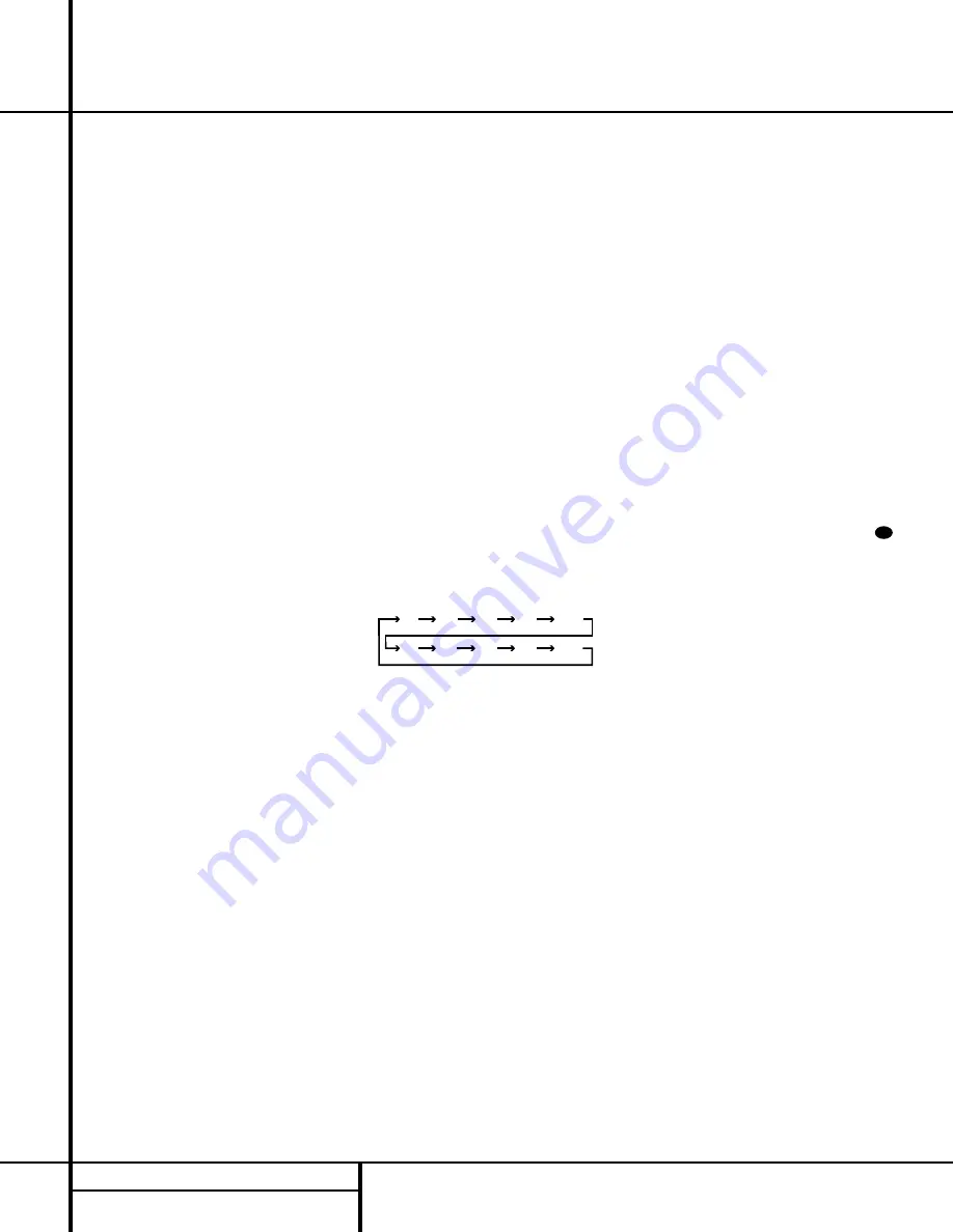
j

Sleep Button:

Press this button to place

the unit in the Sleep mode. After the time
shown in the display, the AVR 510 will auto-
matically go into the Standby mode. Each press
of the button changes the time until turn-off in
the following order:

Note that this button is also used to change
channels on your TV when the TV is selected.

When the AVR 510 remote is being programmed
with the codes to operate another device, this
button is also used in the “Auto Search” process.
(See page 36 for more information on program-
ming the remote.)

k

Surround Mode Selector:

Press this

button to begin the process of changing
the surround mode. After the button has
been pressed, use the 

/

¤

buttons 

n

to

select the desired surround mode. (See page 28
for more information.) Note that this button is
also used to tune channels when the TV is
selected using the device

Input Selector

e

. When the AVR 510 remote is being pro-

grammed with the codes of another device, this
button is also used in the “Auto Search”
process. (See page 36 for more information on
programming the remote.)

l

Night Mode:

Press this button to activate

the Night mode. This mode is available in spe-
cially encoded digital sources, and it preserves

dialog (center channel) intelligibility at low 
volume levels.

m

Channel Select Button:

This button is

used to start the process of setting the AVR 510’s
output levels to an external source. Once this but-
ton is pressed, use the 

/

¤

buttons

n

to

select the channel being adjusted, then press the

Set

button 

p

, followed by the 

/

¤

buttons

again, to change the level setting. (See page 31
for more information.)

n

/

¤

Buttons:

These are multi-purpose

buttons. They will be used most frequently to
select a surround mode. To change the surround
mode, first press the 

Surround Mode 

¤

selector

k

. Next press these buttons to scroll up or

down through the list of surround modes that
appear in the 

Main Information Display 

25

..

These buttons are also used to increase or
decrease output levels when configuring the
unit with either the internal test tone or an
external source. They are also used to enter
delay time settings after the 

Delay

button

has been pressed.

o

Button:

This button is used to change

the menu selection or setting during some of
the setup procedures for the AVR 510.

p

Set Button:

This button is used to enter

settings into the AVR 510’s memory. It is also
used in the setup procedures for delay time,
speaker configuration and channel output level
adjustment.

q

Digital Select:

Press this button to assign

one of the digital inputs 

# %

to a source.

(See page 28 for more information on using
digital inputs.)

r

Numeric Keys:

These buttons serve as a

ten-button numeric keypad to enter tuner preset
positions. They are also used to select channel
numbers when 

TV

has been selected on the

remote, or to select track numbers on a CD,
DVD or LD player, depending on how the
remote has been programmed.

s

Tuner Mode:

Press this button when the

tuner is in use to select between automatic 
tuning and manual tuning. When the button is
pressed so that the 

AUTO

indicator 

X

goes

out, pressing the 

Tuning

buttons 

u8≠

will move the frequency up or down in single-
step increments. When the FM band is in use,
pressing this button when a station’s signal is
weak will change to monaural reception. (See
page 30 for more information.)

30

90

min

80

min

70

min

60

min

50

min

40

min

30

min

20

min

10

min

OFF

Содержание AVR 510

Страница 1: ...AXIAL THEATER 5CHSTEREO HALL12 3 STEREO PROLOGIC DIGITAL DTS DOLBYD PCM MP3 NIGHT MULTI OPTICAL ANALOG OSD LFE 0 C L 0 1 2 3 1 2 3 MEMORY PRESET SLEEP AUTO 5 1 LOGIC 7CM VMAxNF MUTE TUNED ST O O R O O LS O O RS O O Power for the Digital Revolution ...

Страница 2: ...adout 37 Learning Codes 37 Erasing Learned Codes 37 Macro Programming 38 Programmed Device Functions 39 Volume Punch Through 39 Channel Control Punch Through 40 Reassigning Device Control Selectors 41 Function List 43 Setup Code Tables 53 Troubleshooting Guide 53 Processor Reset 54 Notes 55 Technical Specifications AVR 510 Audio VideoReceiver Typographical Conventions In order to help you use this...

Страница 3: ...both composite and S Video inputs Two additional audio inputs are available and a total of six digital inputs make the AVR 510 capable of handling all the latest digital audio sources For compatibility with the latest DVD players and digital video products the AVR 510 also features component video switching Coax and optical digital outputs are available for direct connection to digital recorders a...

Страница 4: ...is exposed to direct sunlight or heating equipment Avoid moist or humid locations Do not obstruct the ventilation slots on the top of the unit or place objects directly over them Cleaning When the unit gets dirty wipe it with a clean soft dry cloth If necessary wipe it with a soft cloth dampened with mild soapy water then a fresh cloth with clean water Wipe dry immedi ately with a dry cloth NEVER ...

Страница 5: ... to select from the choices available as shown in the Main Information Display Û or the on screen displays 6 Tone Mode Pressing this button enables or disables the Bass and Treble tone controls When the button is pressed so that the words TONE IN appear in the Main Information Display Û the settings of the Bass and Treble controls may be used to adjust the output signals When the button is pressed...

Страница 6: ...lso be configured as an output jack to feed a digital signal to a CD R MiniDisc or other digi tal recording device See page 31 for informa tion on configuring the Digital Coax 3 Jack to an output Video 4 Input Jacks These audio video jacks may be used for temporary connection to video games or portable audio video products such as camcorders and portable audio players Bass Control Turn this contro...

Страница 7: ...dicator lights when the Dolby 3 Stereo Mode has been selected I VMAx Mode Indicator This indicator lights when the VMAx mode is in use VMAx F appears when the Far Field VMAx mode is selected VMAx N appears when the Near Field VMAx mode is selected See page 27 for a description of the VMAx modes J 5 Channel Stereo Indicator This indica tor lights when the 5 Channel Stereo mode has been selected K L...

Страница 8: ...r indicator will show the minutes remaining before the AVR 510 goes into the Standby mode See page 26 for more information on the Sleep function U Memory Indicator This indicator flashes when entering presets and other information into the tuner s memory V Stereo Indicator This indicator lights when an FM station is being tuned in stereo W Tuned Indicator This indicator lights when a station is be...

Страница 9: ...uts Tape Outputs Video 1 Audio Inputs AM Antenna Video 1 Audio Outputs DVD Audio Inputs FM Antenna CD Inputs ª 6 Channel Direct Inputs Multiroom Outputs Amplifier Inputs Preamp Outputs Subwoofer Output Video Monitor Outputs fi Speaker Outputs fl Switched AC Accessory Outlet Unswitched AC Accessory Outlet AC Power Cord Component Video Outputs a Video 2 Component Video Inputs b DVD Component Video Inp...

Страница 10: ...t this outlet regard less of whether the AVR 510 is on or off Note The total power consumption of all devices connected to the accessory outlets should not exceed 100 watts AC Power Cord Connect the AC plug to an unswitched AC wall output Component Video Outputs Connect these outputs to the component video inputs of a video projector or monitor When a source connected to one of the two Component V...

Страница 11: ...g AM FM Tuner Select h Learn Button i Test Button j Sleep Button k Surround Mode Selector l Night Mode m Channel Select Button n Buttons o Button p Set Button q Digital Select r Numeric Keys s Tuner Mode t Direct Button u Tuning Up Down v OSD Button w Macro Buttons x Transport Controls y Skip Up Down Buttons z Disc Skip Buttons Preset Up Down 28 Clear Button 29 Memory Button 30 Delay Prev Ch 31 Bu...

Страница 12: ...alibrating the AVR 510 j Sleep Button Press this button to place the unit in the Sleep mode After the time shown in the display the AVR 510 will auto matically go into the Standby mode Each press of the button changes the time until turn off in the following order Note that this button is also used to change channels on your TV when the TV is selected When the AVR 510 remote is being programmed wi...

Страница 13: ...n p and then using the buttons n to change the setting Press the Set button p again to complete the process See page 21 for more information Button Press this button to change a setting or selection when configuring many of the AVR 510 s settings Speaker Select Press this button to begin the process of configuring the AVR 510 s bass management system for use with the type of speakers used in your ...

Страница 14: ...ng one of these buttons will change the input Tuning Up Down Fast Play When this remote is used in the same room as the AVR 510 these buttons may be used to change the frequency of the tuner These buttons may also control the Fast Play or Fast Reverse func tions of compatible Harman Kardon CD DVD or cassette decks in the same room or from a remote room when an IR link is connected to the AVR 510 ƒ...

Страница 15: ... speakers and the receiver the type of speakers you use personal preferences and other factors Your dealer or installer is a valuable resource to consult in selecting the proper cable Regardless of the brand of cable selected we recommend that you use a cable constructed of fine multistrand copper with a gauge of 14 or smaller Remember that in specifying cable the lower the number the thicker the ...

Страница 16: ... formats Component or S Video inputs may only be viewed when the AVR 510 is connected to a TV or video display that is capable of receiv ing that type of signal System and Power Connections The AVR 510 is designed for flexible use with multiroom systems external control compo nents and power amplifiers Main Room Remote Control Extension If the receiver is placed behind a solid or smoked glass cabi...

Страница 17: ...ovide for ultimate flexibility the AVR 510 may be used in conjunction with optional external decoders for digital audio systems other than the AVR 510 s own built in Dolby Digital and DTS decoding system or with DVD players using the DVD Audio Format If an external decoder is used connect the output jacks of the decoder to the 6 Channel Direct Inputs ª making sure to match channels These jacks may...

Страница 18: ...nd right speakers Surround speakers should be placed on the side walls of the room at or slightly behind the listening position The center of the speaker should face into the room The speakers should be located so that the bottom of the cabinet is at least two feet higher than the listeners ears when the listeners are seated in the desired area If side wall mounting is not practical the speakers m...

Страница 19: ...hat when the full OSD system is in use the menu selections are not shown in the Main Information Display Û Y When the full OSD menu system is used OSD ON will appear in the Main Information Display Y and the OSD Indicator M will light to remind you that a video display must be used When the semi OSD system is used in conjunction with the discrete configuration buttons the on screen display will sh...

Страница 20: ...is normally an input but this may also be switched to a digital output for use with CD R RW decks MD recorders or other A V recorders To change the jack to an output press the buttons n while the IN OUT SETUP menu is on the screen until the cursor is next to COAXIAL 3 Then press the buttons o so that the word OUT is highlighted Note that the Input Output Status Indicator will turn red indicating t...

Страница 21: ...nd Theater modes use a fixed nonadjustable delay time The Dolby Digital mode also includes a separate setting for the Center Channel Delay mode since the discrete nature of these signals makes the location of the center channel speaker more critical To calculate the delay for the center channel measure the distance from the pre ferred listening position in the center of the room to both the center...

Страница 22: ...els When LARGE is selected a full range output will be sent to the front left and front right outputs Depending on the choice made in the SUBWOOFER line in this menu bass information may also be directed to the front left right speakers a subwoofer or both When you have completed your selection for the front channel press the button n on the remote to move the cursor to CENTER Press the buttons o ...

Страница 23: ...ut using the full OSD on screen menu system by pressing the Speaker Select button on the front panel ı or remote Once the button is pressed FNT SPEAKER will appear in both the lower third of the video display and the Main Information Display Y Within three seconds either press the front panel Selector buttons 5 or the buttons n on the remote to select a different speaker position or press the Set ...

Страница 24: ...ing 7 After the test noise has circulated once through each channel it will send the tone to each channel once again to verify the settings 8 After two complete circulations of the tone the levels are set The Program SPL Indicator c will remain green at each channel Upon completion of the second circulation the Program SPL Indicator c will flash green twice and then go out The tone will stop and t...

Страница 25: ...e the test noise is circulating the proper channel position will also be indicated in the Speaker Channel Input Indicators Q by a blinking letter within the correct channel To adjust the output level press the Selector buttons 5 on the front panel or the buttons o until the desired level is shown in the display or on screen Once the buttons are released the test noise will begin to circulate again...

Страница 26: ...nt panel Input Source Selector button Each press of the button will move the input selection through the list of available inputs As the input is changed the AVR 510 will automatically switch to the digital input if selected surround mode speaker configura tion output levels crossover frequency and night mode status that were entered during the configuration process for that source The front panel...

Страница 27: ...presenting a wider front soundstage and greater rear ambience Both Logic 7 modes also direct low frequency information to the subwoofer if installed and configured to deliver maximum bass impact DOLBY 3 STEREO Uses the information contained in a surround encoded or two channel stereo program to No surround channels create center channel information In addition the information that is normally sent...

Страница 28: ...eft surround and right surround Each channel repro duces full frequency range 20Hz to 20kHz and offers dramatically improved dynamic range and significant improvements to signal to noise ratios In addition digital systems have the capability to deliver an additional channel that is specifically devoted to low frequency information This is the 1 channel referred to when you see these sys tems descr...

Страница 29: ... a standard analog signal is in use only the L and R indicators will light as analog signals have only left and right channels Digital signals however may have two five or six separate channels depending on the pro gram material the method of transmission and the way in which it was encoded When a digi tal signal is playing the letters in these indica tors will light in response to the specific si...

Страница 30: ...gnal is interrupted for any reason such as stopping the source device upon resumption of the signal the AVR 510 will use a different surround mode In fact the AVR 510 will use whichever mode was set as the default for that source The factory default for all sources is Stereo mode unless the receiver detects a Dolby Digital or DTS bitstream MP3 Audio Playback The AVR 510 is one of the first A V rec...

Страница 31: ...which input you wish to change to an output Either input or both may be changed at any time 4 Press the Set button p and then press either of the buttons o so that the word IN is highlighted 5 Press the Set button p to enter the change 6 Press the OSD button v to exit the menus and return to normal operation Note that once the setting is made the appro priate Input Output Status Indicator will tur...

Страница 32: ...ENU and then press the Set Button p if you wish to go back to the main menu to make other adjustments If you have no other adjustments to make press the OSD button v to exit the menu system NOTE The output levels may be separately trimmed for each digital and analog surround mode If you wish to have different trim levels for a specific mode select that mode and then follow the instructions in the ...

Страница 33: ... to the ADVANCED line Press the Set button p to enter the ADVANCED SELECT menu Figure 9 At the ADVANCED SELECT menu make certain that the on screen cursor is next to the VOLUME DEFAULT line by pressing the buttons n as needed Next press the button so that the word ON is highlighted in the video display Next press the button n once so that the on screen cursor is next to the DEFAULT VOL SET line To...

Страница 34: ... screen for 20 seconds after a period of inactivity before they disappear from the screen Time Out Time Out is a safety measure to prevent image retention of the menu text in your monitor or projector which might happen if it were left on indefinitely However some viewers may prefer a slightly longer or shorter period before the Time Out display To change the Full OSD Time Out you will need to mak...

Страница 35: ...e As long as an IR feed to the AVR 510 has been established from the remote room using any of the buttons on either remote will control the remote location volume î change the tuner frequency uç change the tuner preset or mute the output If the Remote IR Output jack c on the AVR 510 is connected to an IR Input jack on compatible Harman Kardon audio components such as CD DVD or cassette players the...

Страница 36: ...or if not all functions operate properly try programming the remote with the Auto Search Method Auto Search Method If the unit you wish to include in the AVR 510 s remote is not listed in the code tables in this manual or if the code does not seem to operate properly you may wish to program the correct code using the Auto Search method that follows 1 Turn on the unit that you wish to include in th...

Страница 37: ...buttons 3 Press and release the Input Selector efg again for the device within which the individual button to be erased has been programmed 4 Press the 7 button r four times 5 Press and release the individual button for which the code is to be erased The Program SPL Indicator c will blink green two times and then return to amber 6 To erase other buttons within the same device press them as noted i...

Страница 38: ...510 s remote has been pro grammed for the codes of other devices press the appropriate Input Selector e to change the remote from controlling the AVR 510 to con trolling the additional product When you press any one of the selectors it will briefly flash in red to indicate that you have changed the device being controlled When operating a device other than the AVR 510 the controls may not correspo...

Страница 39: ... remote For example while using and controlling the VCR you may wish to change channels on a cable box or satellite receiver without having to change the device selected by the AVR 510 or the remote To program the remote for Channel Control Punch Through follow these steps 1 Press the Input Selector button e for the device you wish to have the channel control associated with and the Mute button at...

Страница 40: ... second VCR first press the CBL SAT Input Selector e and the Mute button at the same time until the red light glows under the CBL SAT e button Press the VCR e button followed by the three digit code for the specific model you wish to control Finally press the CBL SAT e button again Resetting the Remote Memory As you add components to your home theater sys tem occasionally you may wish to totally r...

Страница 41: ... TV VCR TV Cable TV Sat 19 Volume Up Volume Up Input Level Up Volume Up Volume Up Volume Up Volume Up 20 Surround Select Surround Mode Select CDR Select Channel Channel Channel 21 Night Night Mode Select 22 Multi Room Multi Room Select 23 Volume Down Volume Down Input Level Down Volume Down Volume Down Volume Down 24 Channel Guide Channel Trim Title Info Guide Info Guide 25 Move Adjust Up Up Up Up...

Страница 42: ... Rev Intro Scan 53 M1 Open Close Open Close Cancel Sleep PPV Cancel 54 M2 Subtitle On Off Repeat Fav Fav 55 M3 Audio Select Random Play Bypass Next 56 M4 Angle Select Music Alt 57 Rewind R Search R Search Rewind Rewind Day Day 58 Play Play Play Play Play 59 Fast Forward F Search F Search Fast Fwd Fast Fwd Day Day 60 Record Record Record Record 61 Stop Stop Stop Stop Stop 62 Pause Pause Pause Pause...

Страница 43: ...LINK 200 DYNASTY 045 DYNATECH 063 ELECTROHOME 074 132 EMERSON 001 012 033 045 048 049 051 052 091 107 132 137 139 141 157 158 162 205 FISHER 013 058 FUNAI 033 045 FUTURETECH 045 GE 001 014 015 038 057 070 071 107 121 133 141 145 163 199 GOLDSTAR 011 093 097 101 103 104 107 110 113 118 128 132 GRUNDIG 193 HALL MARK 107 HARMAN KARDON 201 HITACHI 001 011 015 016 017 018 029 043 072 132 144 147 INFINI...

Страница 44: ...5 048 195 196 197 RUNCO 152 153 SAA 183 SAMPO 001 059 107 SAMSUNG 051 085 092 096 104 107 118 124 128 132 145 SANYO 013 026 027 037 041 054 058 078 SCOTT 033 045 049 107 132 SEARS 011 013 021 033 035 058 078 092 107 132 145 SHARP 011 020 025 028 033 034 077 132 154 SIEMENS 084 SIGNATURE 069 SONY 043 067 075 117 130 136 194 212 SOUNDESIGN 003 033 045 107 SPECTRICON 103 SSS 011 045 SUPREMACY 002 SYL...

Страница 45: ...19 FERGUSON 136 FINLUX 133 FISHER 003 015 016 017 FUNAI 040 133 GE 037 039 067 076 093 095 124 127 GO VIDEO 113 117 GOLDSTAR 018 019 026 087 092 100 107 GRAETZ 136 HARMAN KARDON 018 049 HITACHI 011 040 048 067 118 130 INSTANT REPLAY 037 039 ITT 136 JCL 037 039 JC PENNEY 018 019 021 039 045 070 087 JENSEN 048 JVC 018 037 039 048 052 054 059 064 111 130 132 KENWOOD 020 044 048 052 LLOYD 040 LXI 019 ...

Страница 46: ...099 101 105 106 109 SANSUI 028 048 052 116 147 166 SANYO 003 014 017 020 115 SCHAUB LORENZ 136 SCOTT 023 043 098 110 112 SEARS 003 015 016 017 019 020 026 037 047 077 084 087 SHARP 037 058 129 156 SHINTOM 030 SONY 003 016 037 056 060 061 062 080 081 082 129 SOUNDESIGN 040 STS 019 SYLVANIA 037 039 040 063 071 SYMPHONIC 040 TANDY 017 040 TASHICO 134 TATUNG 044 048 TEAC 040 044 048 TECHNICS 037 039 T...

Страница 47: ...52 093 108 FISHER 023 055 057 068 FRABA 117 FUNAI 126 GE 164 GENEXXA 017 096 108 GOLDSTAR 016 087 HAITAI 099 214 HARMAN KARDON 001 002 025 040 054 190 218 219 HITACHI 049 093 INKEL 026 027 216 JC PENNEY 021 066 098 147 JENSEN 153 JVC 029 176 195 196 KENWOOD 014 020 023 030 062 078 079 148 151 176 178 181 KYOCERA 012 LOTTE 108 LUXMAN 018 035 077 102 LXI 066 164 MAGNAVOX 039 051 113 MARANTZ 043 051 ...

Страница 48: ...3 095 104 105 108 164 166 ROTEL 051 SAE 051 SAMSUNG 028 SANSUI 047 051 081 134 157 172 SANYO 033 057 068 082 095 168 SCOTT 108 SEARS 066 SHARP 020 058 073 105 114 151 159 167 180 181 SHERWOOD 003 026 027 041 058 105 133 SIGNATURE 040 SONY 060 103 115 116 118 132 139 163 205 206 207 208 212 217 SOUNDSTREAM 124 STS 012 SYLVANIA 051 SYMPHONIC 059 110 TAEKWANG 177 TANDY 096 TEAC 011 022 048 058 085 08...

Страница 49: ...05 HARMAN KARDON 001 032 JVC 006 KENWOOD 007 050 LG 005 055 064 LOTTE 008 MAGNAVOX 033 056 MARANTZ 033 059 MITSUBISHI 023 036 NAD 010 062 ONKYO 009 015 048 OPTIMUS 011 050 PANASONIC 024 025 030 034 035 044 052 PHILIPS 033 056 PIONEER 012 020 038 041 046 047 065 PROCEED 060 PROSCAN 003 004 037 RCA 003 004 018 037 RUNCO 027 SAMSUNG 031 053 054 SANYO 013 049 SHARP 021 028 050 SONY 015 029 043 045 TEC...

Страница 50: ...GHES 372 437 HYTEK 359 JANIEL 366 JERROLD 367 454 464 468 KATHREIN 410 LEGEND 453 LUXOR 368 MACOM 317 365 369 370 371 MAGNAVOX 461 473 MEMOREX 453 NEXTWAVE 423 424 NORSAT 373 374 OPTIMUS 466 PANASONIC 366 469 PANASONIC DBS 457 PANSAT 420 PERSONAL CABLE 418 PHILIPS 375 PICO 407 PRESIDENT 326 404 PRIMESTAR 412 454 464 475 RCA 301 408 436 439 458 465 REALISTIC 349 377 480 SAMSUNG 422 442 SATELLITE SE...

Страница 51: ... ELECTRONICS 113 GE 076 GEMINI 015 029 032 060 GENERAL 210 GENERAL INSTRUMENT 168 GOLDEN CHANNEL 037 GOODMIND 112 HAMLIN 055 056 061 099 100 101 117 175 207 208 HITACHI 001 061 188 HOSPITALITY 074 080 JASCO 111 JERROLD 001 002 003 011 015 016 017 073 093 095 096 097 162 167 LINDSAY 118 M NET 043 MACOM 040 191 MAGNAVOX 017 019 068 082 MEMOREX 058 MOVIE TIME 035 039 NSC 022 035 044 075 190 OAK 023 0...

Страница 52: ...3 204 SEAM 121 SHERITECH 029 SIGNAL 037 SIGNATURE 001 188 SL MARX 037 SPRUCER 053 081 177 189 STARCOM 002 011 015 016 163 STARGATE 015 037 120 SYLVANIA 071 TADIRAN 037 TANDY 024 TELECAPATION 028 TEXSCAN 036 071 TFC 122 TIMELESS 123 TOCOM 045 046 062 170 205 TOSHIBA 058 UNIKA 014 021 031 UNITED CABLE 011 059 UNIVERSAL 012 014 021 031 033 034 039 042 113 VIDEOWAY 124 211 VIEWSTAR 019 022 025 086 087...

Страница 53: ...rference Move unit or antenna away from computers fluorescent lights motors or other electrical appliances Letters flash in the channel indicator Digital audio feed paused Resume play for DVD display and digital audio stops Check that Digital Input is selected Processor Reset In the rare case where the unit s operation or the displays seem abnormal the cause may involve the erratic operation of th...

Страница 54: ...54 NOTES Notes ...

Страница 55: ...pedance 1Vp p 75 ohms Output Level Impedance 1Vp p 75 ohms Video Frequency Response 10Hz 8MHz 3dB General Power Requirement AC 120V 60Hz Power Consumption 78W idle 694W maximum 2 channels driven Dimensions Max Width 17 3 inches 440mm Height 6 5 inches 165mm Depth 17 1 inches 435mm Weight 35 lb 15 9 kg Depth measurement includes knobs buttons and terminal connections Height measurement includes fee...

Страница 56: ...250 Crossways Park Drive Woodbury New York 11797 www harmankardon com 2000 Harman Kardon Incorporated Part No J90200012000 ...

Отзывы: