


36
ADVANCED FEATURES
The AVR5000 is equipped with a number of
advanced features that add extra flexibility to
the unit’s operation. While it is not necessary to
use these features to operate the unit, they pro-
vide additional options that you may wish to
use.
Display Brightness
The AVR5000’s front panel
Main Information
Display
Û
is set at a default brightness level
that is sufficient for viewing in a normally lit
room. However, in some home theater installa-
tions, you may wish to occasionally lower the
brightness of the display, or turn it off completely.
To change the display brightness setting for a
specific listening session, you will need to make
an adjustment in the
ADVANC ED
S E L E C T
menu. To start the adjustment,
press the
OSD
button
L
to bring the
MAS-
TER MENU
to the screen. Press the
⁄
Button
D
twice, until the on-screen
›
cursor is
next to the
A DVANCED
line. Press the
Set
Button
F
to enter the
ADVAN C ED
S E L E C T
menu (Figure 9).
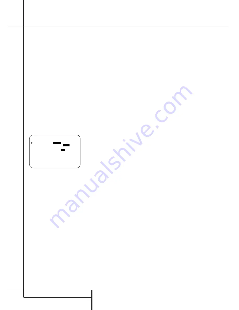
Figure 9
To change the brightness setting, at the
A D V A N C E D S E L E C T
menu, make cer-
tain that the on-screen
›
cursor is next to the
V F D
line, and press the
›
Button
!
until
the desired brightness level is highlighted in the
video display. When
F U L L
is highlighted, the
display is at its normal brightness. When
H A L F
is highlighted, the display is at half the
normal brightness level. When
O F F
is high-
lighted, all of the indicators in the
Main
Information Display
Û
will go dark. Note,
however, that the green LEDs for the
Input
Indicators
and the
Surround Mode
Indicators
˜
, as well as for the
Power
Indicator
3
, will always remain lit to remind
you that the unit is turned on.
If you wish to make other adjustments in the
menu, press the
⁄
/
¤
Buttons
D
until the on-
screen
›
cursor is next to the desired setting or
the
R E T U R N T O M E N U
line and press
the
Set
button
F
. If you have no other adjust-
ments to make, press the
OSD
Button
L
to
exit the menu system.
The display brightness may also be changed by
pressing and holding the
Set
button
Ô
on the
front for three seconds until the message in the
Main Information Display
Y
reads
V F D
F U L L
. Within five seconds, press the front
panel
Selector
buttons
5
until the desired
brightness display level is shown. At that point,
press the
Set
button
Ô
again to enter the
setting.
Once the desired brightness level is selected, it
will remain in effect until it is changed again or
until the unit is turned off.
Turn On Volume Level
As is the case with most audio/video receivers,
when the AVR5000 is turned on, it will always
return to the volume setting in effect when the
unit was turned off. However, you may prefer to
always have the AVR5000 turn on at a specific
setting, regardless of what was last in use when
the unit was turned off. To change the default
condition so that the same volume level is
always used at turn-on, you will need to make
an adjustment in the
A D V A N CE D
S E L E C T
menu. To start the adjustment,
press the
OSD
button
L
to bring the
MAS-
TER MENU
(Figure 1) to the screen. Press
the
⁄
button
D
twice, until the on-screen
›
cursor is next to the
A D V A N C ED
line. Press
the
Set
button
F
to enter the
ADVANCED SELECT
menu (Figure 9).
At the
A D V A N C E D S E L E C T
menu
make certain that the on-screen
›
cursor is next
to the volume default line by pressing the
⁄
/
¤
buttons
D
as needed. Next, press the
›
but-
ton
!
so that the word
O N
is highlighted in
the video display. Next, press the
¤
button
D
once so that the on-screen
›
cursor is next to
the
D E F A U L T V O L S E T
line. To set the
desired turn-on volume, press the
‹
/
›
buttons
E!
or hold them pressed until the desired
volume level is shown on the
D E F A U L T
V O L S E T
line. Note that this setting may
NOT be made with the regular volume controls.
NOTE
: Since the setting for the turn-on volume
cannot be heard while the setting is being made,
you may wish to determine the setting before
making the adjustment. To do this, listen to any
source and adjust the volume to the desired
level using the regular volume controls
Ó
$
î
. When the desired volume level to
be used at turn-on is reached, make a note of
the setting as it appears in the lower third of the
video screen or in the
Main Information
Display
Y
(a typical volume level will appear
as a negative number such as -25dB). When
making the adjustment, use the
‹
/
›
buttons
E!
to enter this setting.
Unlike some of the other adjustments in this
menu, the turn-on volume default will remain in
effect until it is changed or turned off in this
menu, even when the unit is turned off com-
pletely.
If you wish to make other adjustments in the
menu, press the
⁄
/
¤
Buttons
D
until the on-
screen
›
cursor is next to the desired setting or
the
R E T U R N T O M E N U
line and press
the
Set
button
F
. If you have no other adjust-
ments to make, press the
OSD
Button
L
to
exit the menu system.
* A D V A N C E D S E L E C T *
V F D :
F U L L
H A L F O F F
V O L U M E D E F A U L T :
O F F
O N
D E F A U L T V O L S E T : 2 5 d B
S E M I O S D : O F F
O N
S E M I O S D T I M E O U T : 3 5
F U L L O S D T I M E O U T : 2 0 5
R E T U R N T O M E N U
Advanced Features


