


SYSTEM CONFIGURATION
SYSTEM CONFIGURATION
SYSTEM CONFIGURATION 27
SYSTEM CONFIGURATION 27
by reading the messages that appear in the second
line of the menu listing. When the EzSet/EQ screen
first appears, it contains a series of dashes, but as
the test and measurement proceeds, you will see the
following messages as the individual measurements
are taken:
•
System Level:
A
SETTING VOLUME
message will appear to indicate that the system is
setting the overall volume level to the proper level
as a prelude to testing the individual channels.
During this test, you will see this line of the menu
screen change as the volume level is adjusted.
•
Speaker Check:
The system will circulate a test
signal to determine which channels have a speaker
connected. During this test, you will see the name
of each channel position displayed while a signal is
sent to that speaker.
NOTE:
While this test detects whether a speaker is
connected to a particular output, it cannot determine
whether the speaker is in the correct position. (For
example, it can tell whether a speaker is connected
to the Surround Right output, but it cannot tell
whether the speaker is on the right or left side of
your listening room.) For that reason, we strongly
recommend that you try to listen as the tone circu-
lates, matching the name shown for each channel to
the location of the speaker. If a tone is heard from a
speaker position that does not match the on-screen
message, stop EzSet/EQ, exit the menus, turn your
receiver off and check for proper speaker connec-
tions on the rear panel before resuming the setup.
When this test is complete,
YES
will be shown
to the right of
SPEAKER CHECK
on the
menu screen.
•
Speaker Delay:
This test will circulate the tones
again as the name of each channel is shown to
measure the distance from the microphone to each
speaker. The results of these tests will be used to
set the delay time settings for each active speaker
position. When this test is complete, a speaker-to-
microphone (listening position) distance will be
shown to the right of the
SPEAKER DELAY
line on the menu screen.
NOTE:
A/V Sync Delay may only be set manually
(see page 30).
•
Speaker Level:
This test circulates a test signal
and measures the output from each active speaker
position. The results of the measurements are used
to adjust the individual channel outputs as needed,
so that they are identical. This is an essential ele-
ment of ensuring that surround sound fields are
properly reproduced. If desired, you may use the
results of the automated testing as a baseline and
then make manual adjustments to trim the output
levels to your personal taste, following the instruc-
tions shown on page 31 or 42. When this test is
complete, an output level adjustment number will be
shown to the right of the
SPEAKER LEVEL
line on the menu screen.
•
Speaker Size:
The measurements and calculations
for this test take place at the same time as the test
signals are circulated to calculate the output levels,
and they are used to determine whether the speakers
in your system are “large” or “small” for the purposes
of bass management. (If desired, you may use the
results of the automated testing as a baseline and
then make manual adjustments to the speaker size
settings independently for each source, following the
instructions shown on page 28.) When this test is
complete, an output level adjustment number will be
shown to the right of the
SPEAKER SIZE
line on the menu screen.
•
Speaker Crossover:
The measurements and cal-
culations for this test take place at the same time as
the test signal is circulated to calculate the levels,
and they are used to determine the crossover set-
ting for each speaker in your system to create a
seamless transition between the frequencies sent to
your main speakers and subwoofer (if available). If
desired, you may use the results of the automated
testing as a baseline and then make manual adjust-
ments to the crossover settings, following the
instructions shown on page 30. When this test is
complete, a crossover frequency will be shown to
the right of the
SPEAKER X-OVER
line
on the menu screen.
•
Room Equalization:
Each room has unique char-
acteristics that may affect the frequency response at
the listening position. For example, doorways and
alcoves can increase bass response nearby. Various
surfaces such as hard floors or windows, or soft
carpets or draperies, may also affect the way the
room responds to sound. Until now, expensive test-
ing devices and long hours of taking measurements
and adjusting room furnishings were required in
order to smooth out the frequency response to
avoid artifacts. EzSet/EQ simplifies equalization,
delivering world-class performance without the extra
expense. While the test tone circulates, EzSet/EQ is
able to obtain a sonic “view” of the room and its
characteristics, and adjust the receiver’s output
accordingly to customize performance to the
listening room.
Step 9:
When all measurements are successfully
completed, the test signals will stop and a
TEST
DONE Ð UNPLUG MIC
message will appear
in the second line. The cursor will pause at
SAVE
SETTINGS
, allowing you the option of selecting
YES
or
NO
. Unplug the microphone and store it in
a safe place so that it is available to recalibrate your
system if needed due to a change in speakers, pre-
ferred listening position, or a major change in the
room’s furnishings (such as the addition of thick car-
peting or plush furniture) that might require different
settings. To enter the settings to the receiver’s memory
and return to the Master Menu, make sure that
YES
appears at the
SAVE SETTINGS
line, press
the
⁄
/
¤
Buttons
n
so that the on-screen cur-
sor is pointing to
RETURN TO MASTER
MENU
and press the
Set Button
p
.
NOTE:
If you wish to check the test results before
exiting the EzSet/EQ menu, press the
⁄
/
¤
Buttons
n
so that the on-screen cursor is at the
second line of the menu listings, and then press the
‹
/
›
Buttons
o
to scroll through the list of speaker
positions. The data on each line will also be entered
into the listings on the individual
SPEAKER
SETUP
,
DELAY ADJUST
and
CHANNEL ADJUST
menus once you
exit EzSet/EQ.
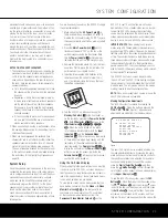
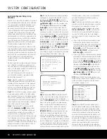
Step 10:
If the measurements are not successful due
to a missing or malfunctioning speaker, an
ERROR
message and menu will appear, as shown in Figure
10. The EzSet/EQ system is programmed to look for
speaker pairs at the front left/front right, surround
left/surround right and surround back left/surround
back right positions. If the tests to any of those three
channel pairs indicates that one, but not
both
of the
speakers in the pair is present, the menu will show
NONE
next to the speaker position where the tests
did not report back that a speaker is present. Should
this message appear, make note of the suspect
speaker location, exit all menus and turn the receiver
off. Check all speaker wire connections and then
rerun EzSet/EQ.
Figure 10
When you have successfully completed the EzSet/EQ
process and made any needed adjustments to the
input and surround mode configurations, your receiver
is ready for use. If you do not wish to make any man-
ual adjustments to the settings, you may skip the rest
of this section and proceed to the Basic Operation
section of this manual on page 34 to learn how to
operate the AVR 340, although we recommend that
you first record your system’s settings using the work-
sheet on page 66 in case the settings need to be
reentered due to a power loss or for some other rea-
son. For those situations where you may wish to make
a change to the settings entered by EzSet/EQ, follow
the instructions on the following pages.
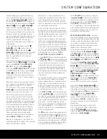
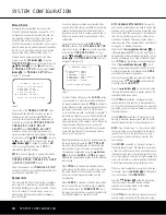
* SPEAKER SIZE *
LEFT/RIGHT:SMALL
CENTER :SMALL
SURROUND :SMALL
SURR BACK :SMALL MAIN
SUBWOOFER :SUB
BASS MGR :GLOBAL
BACK TO MANUAL SETUP
AVR 340 OM 3/22/06 9:09 AM Page 27
Содержание AVR 340
Страница 67: ......


