background image

16

SYSTEM CONFIGURATION

System Configuration

Once the speakers have been placed in the
room and connected, the remaining steps are to
program the system configuration memories.
With the AVR two kind of memories are used,
those associated individually with the input
selected, e.g. surround modes, and others work-
ing independently from any input selected like
speaker output levels, or delay times used by
the surround sound processor.

First Turn On

You are now ready to power up the AVR to
begin these final adjustments.

1. Plug the 

Power Cable

G

into an un-

switched AC outlet.

2. Press the 

Main Power Switch

in until it

latches and the word “OFF” on the top of the
switch disappears inside the front panel. Note
that the 

Power Indicator

2

will turn orange,

indicating that the unit is in the Standby mode.

3. Remove the protective plastic film from the
front-panel lens. If left in place, the film may
affect the performance of your remote control.

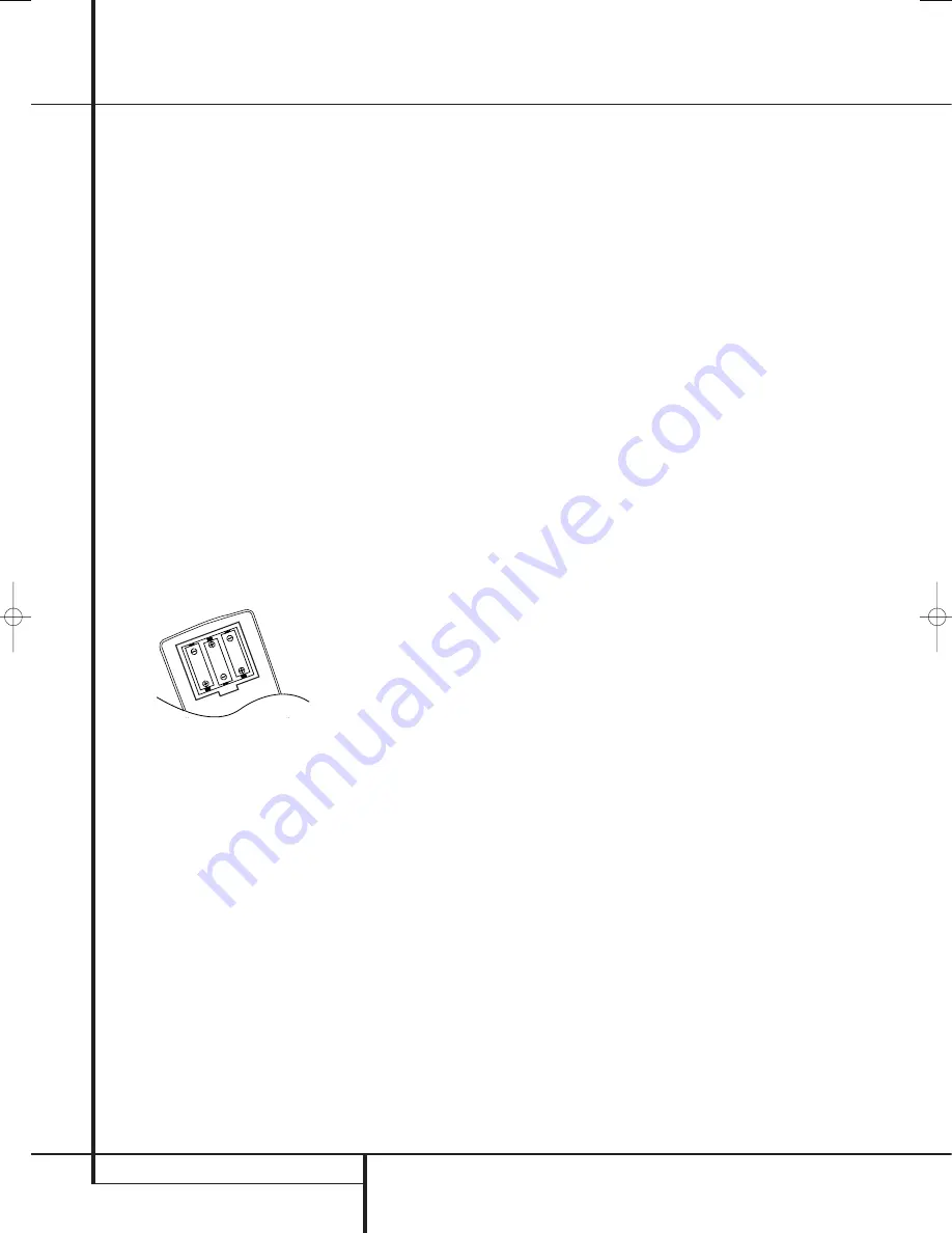
4. Install the three supplied AAA batteries in the
remote as shown. Be certain to follow the (+)
and (–) polarity indicators that are on the bot-
tom of the battery compartment.

5. Turn the AVR on either by pressing the

System Power Control

1

or the 

Input

Source Selector

A

on the front panel, or via

the remote by pressing the 

AVR Selector

5

or any of the 

Input Selectors

46

on the

remote. The 

Power Indicator 

2

will turn blue

to confirm that the unit is on, and the 

Main

Information Display

F

will also light up.

NOTE:

After pressing one of the 

Input Selector

buttons

4

to turn the unit on, press the 

AVR

Selector

5

to have the remote control the AVR

functions.

Settings to be Made With Each
Input Used

The AVR features an advanced memory system
that enables you to establish different settings
for the speaker configuration, digital input, sur-
round mode, delay times and output levels for
each input source. This flexibility enables you to
custom tailor the way in which you listen to each
source and have the AVR memorize them. This
means, for example, that you may associate dif-
ferent surround modes and analog or digital
inputs with different sources, or set different
speaker configurations with the resultant
changes to the bass management system or the
use of the Center speaker. Once these settings
are made, they will automatically be recalled
whenever you select an input.

The default settings for the AVR, as it is shipped
from the factory, have all inputs set for an ana-
log source (except for the DVD input, which has
the 

Coaxial Digital Input 1

9

as the

default), with Logic 7 Music as the surround
mode, all speaker positions set to "small", and a
subwoofer connected. Before using the unit, you
will probably want to change these settings for
most inputs so that they are properly configured
to reflect the use of digital or analog inputs, the
type of speakers installed and the surround
mode associated with the input.

Input Setup

The first step in configuring the AVR is to select
an input. This may be done by pressing the front
panel 

Input Source Selector

A

until the

desired input’s name appears in the 

Main

Information Display

F

, and Indicator will

illuminate next to the input’s name in the front
panel 

Input Indicators

J

. The input may also

be selected by pressing the appropriate Input
Selector on the remote control 

46

.

The second step is to associate one of the digital
inputs with the selected input source (if this is
needed, otherwise the selected analog input will
remain). Press the 

Digital Input Select

button

F

on the remote. Within five seconds, make

your input selection using the 

K

/

L

buttons

C

on the remote until the desired digital or

analog input is shown in the 

Main Infor-

mation Display

F

. Then press the

Set 

button

E

to enter the new digital input assignment.

After the setting has been made with one input,
repeat as described above with all inputs in use.
The digital input associated with the input
selected can also be changed at any time later
and the AVR’s memory system will keep the set-
tings until they are changed again.

Speaker Setup

This setup tells the AVR which type of speakers
are in use. This is important as it adjusts the set-
tings that determine which speakers receive low
frequency (bass) information and whether a

Center speaker should be used or not, separately
for each input used. For each of these settings
use the 

L A R G E

setting if the speakers for a

particular position are traditional full-range
loudspeakers that are capable of reproducing
sounds below 100Hz. Use the 

S M A L L

set-

ting for smaller, frequency-limited satellite
speakers that do not reproduce sounds below
100Hz. Note that when “small” front (left and
right) speakers are used, a subwoofer is
required to reproduce low frequency sounds. If
you are in doubt as to which category describes
your speakers, consult the specifications in the
speakers’ owner’s manual, or ask your dealer.

With the AVR turned on, follow these steps to
configure the speakers:

1. Press the 

Speaker

button 

on the

remote. The words 

SPEAKER SIZE

will

appear in the 

Main Information Display

F

.

2. Press the 

Set

button 

E

.

3. When 

FRONT SPEAKER

appears in the

Main Information Display

F

press the 

Set

button 

E

to continue.

4. Press the 

K

/

L

buttons 

C

on the remote

until either 

FRONT LARGE

or 

FRONT

SMALL

appears, matching the type of speak-

ers you have at the left-front and right-front
positions, as described by the definitions shown
in preceding section.

When 

SMALL

is selected, low frequency front

channel sounds will be sent only to the subwoofer
output. Note that if you choose this option and
there is no subwoofer connected, you will not
hear any low frequency sounds from the front
channels. This setting is not available with stereo
mode to ensure purest sound by bypassing the
crossovers of the DSP´s.

When 

LARGE

is selected, a full-range output

will be sent to the front left and front right out-
puts. Depending on the subwoofer configuration
(see below), the front left and right bass informa-
tion may also be directed to a subwoofer.

Important Note:

When a speaker set with two

front satellites and a passive subwoofer is used,
connected to the 

front speaker outputs

C

,

the fronts must be set for 

LARGE

.

5. When you have completed your selection for the
front channels, press the 

Set

button 

E

, and then

press the 

K

/

L

buttons 

C

on the remote  to

change the display to 

CENTER SPEAKER

.

6. Press the 

Set

button 

E

again, and use the

K

/

L

buttons 

C

on the remote to select the

option that best describes your system based on
the Center speaker definitions shown in preced-
ing section.

When 

SMALL

is selected, low frequency center

channel sounds will be sent to the Fronts, if they

29782_AVR132_ENG  29/11/06  12:07  Side 16

Содержание AVR 132

Страница 1: ...ENGLISH AVR 132 Audio VideoReceiver OWNER S MANUAL...

Страница 2: ...te 29 Programming the Remote with Codes 29 Code Readout 30 Programmed Device Functions 30 Macro Programming 31 Volume Punch Through 31 Channel Control Punch Through 31 Transport Control Punch Through...

Страница 3: ...nd specific listening room environment A Stereo Direct mode bypasses the digital processor to preserve all of the subtleties of older analog two channel materials while bass management available in th...

Страница 4: ...components inside this product Opening the cabinet may present a shock hazard and any modification to the prod uct will void your guarantee If water or any metal object such as a paper clip wire or a...

Страница 5: ...5 Speaker Channel Input Indicators These indicators are multipurpose indicating either the speaker type selected for each channel or the incoming data signal configuration The left cen ter right right...

Страница 6: ...nput sources B RDS Select Button Press this button to display the various messages that are part of the RDS data system of the AVR s tuner See page 28 for more information on RDS C Surround Mode Selec...

Страница 7: ...make connections to the AM and GND terminals in accordance with the instructions supplied with the antenna 4 Video 1 Audio Outputs Connect these jacks to the RECORD INPUT audio jacks on a VCR or any...

Страница 8: ...ct the Y Pr Pb component video outputs of a DVD player to these jacks Note All component inputs outputs can be used for RGB signals too in the same way as described for the Y Pr Pb signals then connec...

Страница 9: ...ttons Transport Controls Skip Up Down Buttons RDS Select Button Preset Up Down Clear Button Memory Button Delay Prev Ch B Button Speaker Select Tone Mode Button Volume Up Down TV Video Selector Mute D...

Страница 10: ...hat this button is also used to tune channels when the TV VCR and SAT receiver is selected using the Input Selector 4 A Night Mode Press this button to activate the Night mode This mode is available o...

Страница 11: ...lence the AVR or TV set being controlled depending on which device has been selected When the AVR remote is being programmed to operate another device this button is pressed with the Input Selector bu...

Страница 12: ...distance between your speakers and the receiver the type of speakers you use personal preferences and other factors Your dealer or installer is a valuable resource to consult in selecting the proper...

Страница 13: ...ce may be assigned to any digital audio input on the receiver 5 Connect the Composite and S Video if S Video device is in use Monitor Output B jacks on the receiver to the composite and S Video input...

Страница 14: ...a VCR connect the Out plugs to the Out jacks on the AVR Note that with some adapter types it may be just turned around If no signal is audible visible when the VCR is playing connect the Out plugs to...

Страница 15: ...ear height when you are seated in the listening position Using these guidelines you ll find that it takes some experimentation to find the correct loca tion for the front speakers in your particular...

Страница 16: ...elected by pressing the appropriate Input Selector on the remote control 46 The second step is to associate one of the digital inputs with the selected input source if this is needed otherwise the sel...

Страница 17: ...front left right main speakers If a subwoofer is connected to the AVR you have the option to have the front left right main speakers reproduce bass frequencies at all times and have the subwoofer ope...

Страница 18: ...nt speakers are band width limited satellite speakers we recom mend that you do NOT use the Bypass mode but rather use the DSP SURROUND OFF mode for stereo listening To listen to programs in the two c...

Страница 19: ...et it is normal for surround speakers to operate only occasionally Artificially increasing the vol ume to the rear speakers may destroy the illu sion of an enveloping sound field that dupli cates the...

Страница 20: ...evel adjust ment made will be effective for the surround mode currently selected also when other inputs are selected using the same surround mode To adjust the output level with all other surround mod...

Страница 21: ...and Video Monitor Output B This permits simultaneous viewing and listening to different sources When a Video source is selected its audio signal will be fed to the speakers and the video signal for t...

Страница 22: ...1 7 1 option is chosen The Logic 7 C or Cinema mode should be used with any source that contains Dolby Surround or similar matrix encoding Logic 7 C delivers increased center channel intelligibility...

Страница 23: ...ts entire path of travel through the receiver to the speaker and subwoofer outputs bypassing all digital processing Digital bass management is not available in Surround Off mode The DSP Surround Off m...

Страница 24: ...TS regardless of the mode that has been previously selected For more information on selecting digital sources see the following section of this manual To listen to a program in traditional two channel...

Страница 25: ...ata An example of this type of display is 3 2 1 The first number indicates how many discrete front channel signals are present A 3 tells you that separate front left center and front right signals are...

Страница 26: ...l mode is turned on using the options in the Night Mode settings See page 19 for infor mation on using this option IMPORTANT NOTES ON DIGITAL PLAYBACK 1 When the digital playback source is stopped or...

Страница 27: ...tion presets and recalled from a 30 position memory Station Selection 1 Press the AM FM Tuner Select button 6 on the remote to select the tuner as an input The tuner may be selected from the front pan...

Страница 28: ...uires a strong enough signal for proper operation Program Search PTY An important feature of RDS is its capability of encoding broadcasts with Program Type PTY codes that indicate the type of material...

Страница 29: ...se a number of different combinations of codes so it is a good idea to make certain that not only does the Power control work but that the volume channel and transport controls work as they should If...

Страница 30: ...erate check to see if another code set will work with more buttons Depending on the brand and product type used the functions listed in the Function List tables may not correspond with the function th...

Страница 31: ...press the VID 1 VCR Input Selector button 4 and the Mute button at the same time Next release them and press the Volume Down button followed by the VID 2 TV Input Selector button 4 NOTE To remove the...

Страница 32: ...peaker Adjust Menu Intro 25 A Left 26 Set Set Enter 27 B Right 28 Digital Exit Digital Input Select Open Close 29 L Move Adjust Down Down 30 Delay Prev Ch Delay Adjust Return Open Close 31 1 1 1 1 32...

Страница 33: ...A Left Left Left Left 26 Set Enter Enter Enter Enter 27 B Right Right Right Right 28 Digital Exit Exit Exit Exit Exit 29 L Down Down Down Down 30 Delay Prev Ch Prev Channel Prev Channel Prev Channel...

Страница 34: ...in Power Switch is pushed into a live outlet Check to see if outlet is switch controlled Display lights but no sound Intermittent input connections Make certain that all input and speaker or picture c...

Страница 35: ...istortion Mono Stereo 0 15 0 3 Stereo Separation 35dB 1kHz Selectivity 400kHz 70dB Image Rejection 80dB IF Rejection 90dB AM Tuner Section Frequency Range 522 1620kHz Signal to Noise Ratio 45dB Usable...

Страница 36: ...50 Crossways Park Drive Woodbury New York 11797 www harmankardon com Harman Consumer Group International 2 route de Tours 72500 Ch teau du Loir France 2006 Harman Kardon Incorporated Part No CQX1A1154...

Отзывы: