


45
●
●
●
●
●
Chapter 6
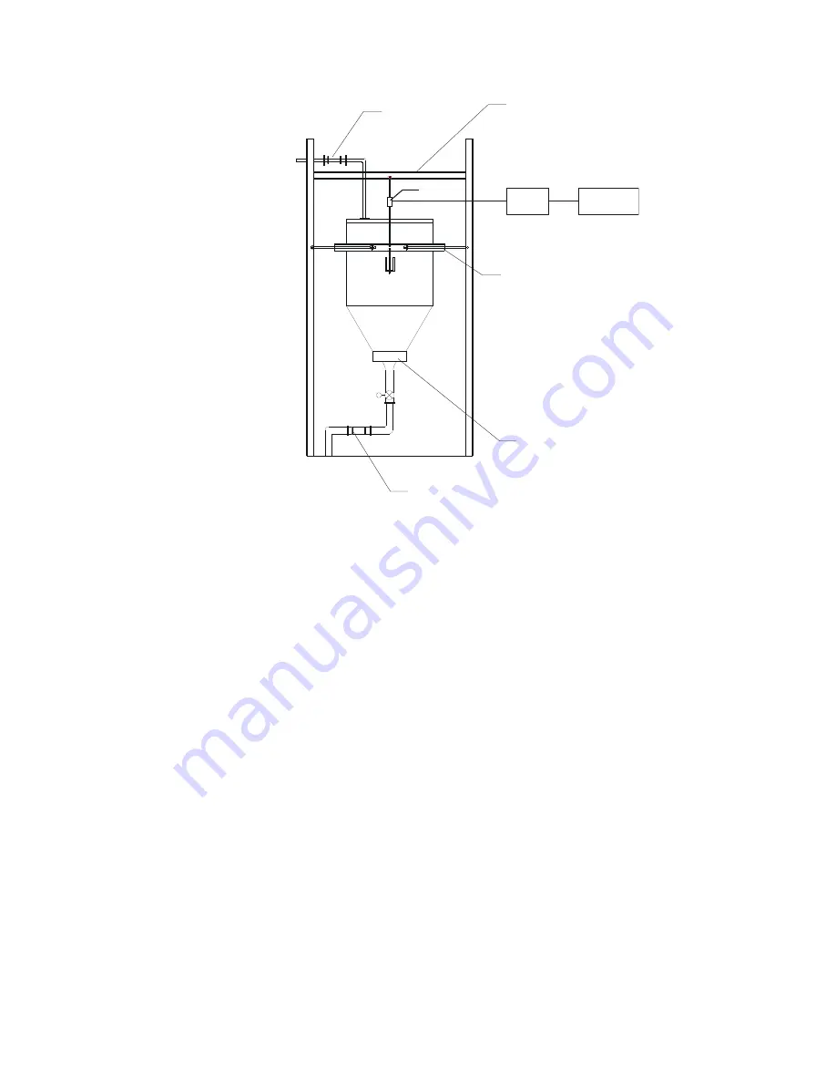
JUNCTION
BOX
INTERMEDIATE SUPPORT FRAME
FULLY CONSTRAINED
LATERALLY WITH STAY RODS
UNIVERSAL JOINT
OR
HOSE
USE SYMMETRIC BEAM LOADED
THROUGH SHEAR CENTER TO
AVOID TWIST WITH LOAD
NON METALLIC EXPANSION
ASSEMBLY OR HOSE
BIN ACTIVATOR
HI 4060
Rate Controller
The load cell/point takes as an input the 5 volts DC excitation voltage generated by the
HI 1756-FC. It generates a millivolt output proportional to the weight on the scale (0-
10mV DC for 2mV/V load cells/points or 0-15mV DC for 3mV/V load cells/points).
Rate Controller
- is the part of the HI 1756-FC instrument that, among other functions:
Powers the load cell(s)/point(s)
Reads the millivolt signal output from the load cell(s)/point(s)
Digitizes, interprets, communicates the results in terms of weight and rate
INTEGRATED TECHNICIAN (IT®)
INTEGRATED TECHNICIAN (IT®) is a diagnostics utility that enables the operator to
rapidly troubleshoot the individual load cells in a weighing system. An HI 215IT
Summing junction box is required to read data for individual load points. It provides
separate inputs for each load cell.
If you have more than one load cell without the IT junction box, there is no easy way to
isolate the load cell signals.
If you have more than one load cell with the IT junction box, the system can provide both
the average numerical values and values specific to each load cell. The number for a load
sensor is based on the connections in the IT junction box.
Check the installation sequence in the box to determine which load sensor is number 1, 2
and so on. Always install the first load cell in position 1.
If you do not have the optional IT junction box, some of the options described below will
not appear on either interface.
Warning
Do not install your junction box in areas that are susceptible to high vibrations since the
relays on the summing board can “chatter” and affect your weight readings.


