6 - Maintenance
141
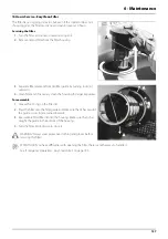
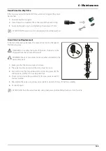
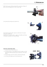
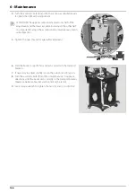
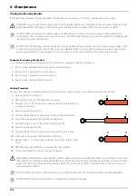
With the locking piece (B) removed, place the screw driver as shown and
pull to remove the upper part (C) of the nozzle holder.
Locking piece (B) and upper part separated (C).
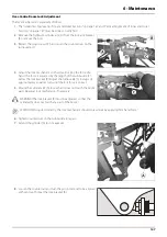
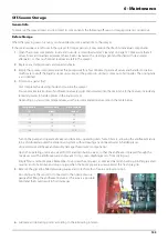
Inside the lower part (D), the O-ring (E) is located, and it can now be
removed for maintenance.
Note that the O-ring, when seated, is supposed to be a little out of shape
to fit tightly around the hole in the nozzle pipe.
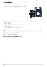
How To Reassemble Nozzle Holder
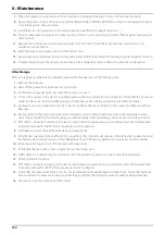
1.
Place the O-ring inside the lower part.
2.
Place the lower part on the nozzle pipe. The O-ring fits around the
hole in the nozzle pipe, where the spray liquid exits to the nozzle
holder.
3.
Place the upper part on the opposite side of the nozzle pipe.
4.
Click the parts together by pressing relatively hard.
Содержание MEGA VPZ MASTER
Страница 1: ...MEGA VPZ Original Instruction book 67050600 110 version 1 10 GB 03 2018 www hardi international com...
Страница 4: ...1 EU Declaration 4...
Страница 10: ...Table of Contents 10...
Страница 42: ...2 Safety Notes 42...
Страница 68: ...3 Description 68...
Страница 118: ...5 Operation 118...
Страница 121: ...6 Maintenance 121 Lubrication Plan Boom Centre Close up of Glide Shoes to be Lubricated...
Страница 122: ...6 Maintenance 122 Lubrication Plan Boom Wings Both boom wings left and right are to be lubricated equally 10...
Страница 172: ...8 Technical Specifications 172...
Страница 176: ...Index 176...
Страница 178: ...HARDI INTERNATIONAL A S Herthadalvej 10 DK 4840 N rre Alslev DENMARK...

