background image


CAUTION:

 Be sure outlet box is properly 

grounded and that a ground (green or bare) wire is 
present.

       WARNING:

 If house wires are different colors than 

referred to in the following steps, stop immediately. A 
professional electrician is recommended to determine 
wiring.

WIRING


DANGER:


If using this fan in a DAMP location, this 

fan must be connected to a supply circuit that is protected 
by a Ground Fault Circuit Interrupter (GFCI) to reduce the 
risk of personal injury, electrical shock or death.

10

Lowes.com/harborbreeze


WARNING:

  To reduce the risk of fire, electrical 

shock, or personal injury, wire connectors provided 
with this fan are designed to accept only one 
12-gauge house wire and two lead wires from the 
fan. If your house wire is larger than 12-gauge or 
there is more than one house wire to connect to the 
corresponding fan lead wires, consult an electrician 
for the proper size wire connectors to use.

 1. 

1

WHITE SUPPLY WIRE

BLACK SUPPLY WIRE

BLACK

BLACK

WHITE

BLUE

BLUE

WHITE

BLACK

AC IN L

AC IN N

WHITE

WHITE

GROUND (GREEN
OR BARE)

FROM FAN

FROM RECEIVER

ANTENNA

FROM

 CEILING

BLACK

FROM RECEIVER

Make the necessary wiring connections for remote 
control operation according to Fig. 1. For each wire 
connection, use one of the wire connectors (AA) 
provided, making sure to screw wire connector (AA) 
on in a clockwise direction. [Make sure to connect 
all 

GROUND

 (

GREEN

) wires together from fan (on 

downrod (A) and mounting bracket C)) to 

BARE

/

GREEN

 wire from ceiling.]

WIRING TIP:

 Wiring your fan's remote control 

requires extreme patience. Take mandatory breaks 
while wiring to allow your arms to rest.

NOTE:

 Black and blue wires are hot power for fan. 

White wire is common for fan. Green or bare wire is 
ground.

NOTE:

 Please refer to installation and operating 

instructions for remote control.

J

Содержание CE-JP13EB6RC

Страница 1: ...ved ITEM 0428798 MODEL CE JP13EB6RC Questions problems missing parts Before returning to your retailer call our customer service department at 1 800 643 0067 8 a m 6 p m EST Monday Thursday 8 a m 5 p...

Страница 2: ...this fan need to be returned to the factory for repairs it must be shipped in its original packaging to ensure proper protection against damage that might exceed the initial cause for return Make sure...

Страница 3: ...consult an electrician for the proper size wire connectors to use To reduce the risk of fire or electrical shock do not use the fan with any solid state speed control device or control fan speed with...

Страница 4: ...acket 1 D Motor Assembly 1 E Pin preassembled 1 F Clip preassembled 1 G Canopy Mounting Screw 2 preassembled H Canopy Cover 1 I Remote Control 1 Transmitter J Remote Control Receiver 1 K Battery 1 L Y...

Страница 5: ...outlet box is securely attached to the building structure and can support the full weight of the fan Failure to do this can result in serious injury or death The stability of the outlet box is essenti...

Страница 6: ...ll fans will be at least 30 in from any obstruction Check downrod A length to ensure blades will be at least 10 ft above the floor when smaller fans are in fully tilted position 3 6 Lowes com harborbr...

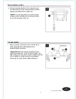
Страница 7: ...a longer downrod not included A longer downrod is sometimes necessary to ensure proper blade clearance 1 Secure mounting bracket C to outlet box not included using screws spring washers and flat washe...

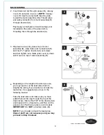
Страница 8: ...d wires Steps 4 and 5 are not necessary and you may proceed to Step 6 instead 4 2 Insert downrod A through canopy B canopy cover H and yoke cover L NOTE Canopy cover H must be turned with the shiny si...

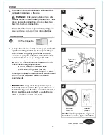
Страница 9: ...ther person to hold the stepladder in place and to then help lift the fan up to you once you are set on the ladder 6 If you decided to cut back the lead wires in Step 4 strip a 1 2 in of insulation fr...

Страница 10: ...re to connect to the corresponding fan lead wires consult an electrician for the proper size wire connectors to use 1 1 WHITE SUPPLY WIRE BLACK SUPPLY WIRE BLACK BLACK WHITE BLUE BLUE WHITE BLACK AC I...

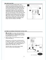
Страница 11: ...Wrap electrical tape around each individual wire connector AA down to the wire WARNING Make sure no bare wire or wire strands are visible after making connections Place green and white connections on...

Страница 12: ...rn wall switch off to any other programmable receiver or fan 1 Code Switches Battery Cover I 1 FINAL INSTALLATION Locate two canopy mounting screws G on underside of mounting bracket C and remove cano...

Страница 13: ...gital device pursuant to Part 15 of the FCC Rules These limits are designed to provide reasonable protection against harmful interference in a residential installation This equipment generates uses an...

Страница 14: ...smaller fans to LOW speed Button turns the 2 smaller fans OFF Button turns main fan ON OFF when pressed once i e controls ROTATION of the ENTIRE fan 1 1 I The tilt angle of the smaller fans may be ad...

Страница 15: ...er I may not have been successful and learning code was not activated 1 Turn power on or check fuse or breaker 2 Turn power off Loosen canopy B and check all connections 3 Turn off power and repeat in...

Страница 16: ...ranty does not cover changes in brass finish rusting pitting tarnishing corroding or peeling Brass finish fans maintain their beauty when protected from varying weather conditions Any glass provided w...

Страница 17: ...mitter J Remote Control Receiver L Yoke Cover AA E3 Wire Connector AA J REPLACEMENT PARTS LIST For replacement parts call our customer service department at 1 800 643 0067 8 a m 6 p m EST Monday Thurs...

Отзывы: