background image

7

Lowes.com/harborbreeze

INITIAL INSTALLATION

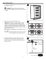
1.  Turn off the circuit breakers and the wall switch to the 

fan supply line leads.


DANGER:

 Failure to disconnect the power 

supply prior to installation may result in serious injury 

or death.

1

2.  Determine the mounting method to use.

Helpful Hint:

 Downrod mounting is best suited for 

ceilings 8 ft. or higher. For taller ceilings you may 

want to use a longer downrod (not included). Angle 

mounting is best suited for angled or vaulted ceilings. 

A longer downrod is sometimes necessary to ensure 

proper blade clearance.

Note:

 Flushmount installation is not available for this 

item.

Important:

 If using the angle mount, check to ensure 

the ceiling angle is not steeper than 23°.

2

Downrod Mounting

Flushmount 

Closemount 

Angle Mounting

3.  Ensure the blades (I) will be at least 30 in. from 

any obstructions. Also check the downrod (A) 

length to ensure the blades (I) will be at least 7 ft. 

above the floor.

I

A

3

7 ft.
Minimum

30 in. 

Minimum

Содержание ARMORY 40087

Страница 1: ...00 643 0067 8 a m 6 p m EST Monday Thursday 8 a m 5 p m EST Friday ATTACH YOUR RECEIPT HERE Serial Number _________________________ Purchase Date _________________________ Harbor Breeze is a registere...

Страница 2: ...ts 4 Safety Information 5 Preparation 6 Initial Installation 7 Standard or Angle Mounting Instructions 9 Closemount Instructions 12 Final Installation 15 Operating Instructions 17 Care and Maintenance...

Страница 3: ...A Downrod 1 B Canopy preassembled to Mounting Bracket C 1 C Mounting Bracket 1 D Yoke Cover 1 E Motor Assembly 1 F Fitter Plate preassembled to Motor Assembly E 1 G Canopy Cover preassembled to Canopy...

Страница 4: ...n Qty 1 preassembled to Downrod A Motor Housing Set Screw Qty 2 preassembled to Motor Assembly E Closemount Screw Qty 3 1 extra Mounting Bracket Screw Qty 4 preassembled to Mounting Bracket C Blade Sc...

Страница 5: ...rsonal injury mount the fan to an outlet box marked ACCEPTABLE FOR FAN SUPPORT and use the mounting screws provided with the outlet box Most outlet boxes commonly used for the support of lighting fixt...

Страница 6: ...all parts are present Compare all parts with the package contents list and hardware contents list If any part is missing or damaged do not attempt to assemble the product After opening the top of the...

Страница 7: ...ant to use a longer downrod not included Angle mounting is best suited for angled or vaulted ceilings A longer downrod is sometimes necessary to ensure proper blade clearance Note Flushmount installat...

Страница 8: ...ting bracket C to the outlet box using screws and washers provided with the outlet box Hardware Used HH Mounting Bracket Screws x 2 C 4 B HH C 5 Remove and discard the three rubber stoppers and five p...

Страница 9: ...m the mounting bracket C to the White common supply wire Secure all wiring connections together with wire connectors BB Note The Black wire is hot power for the fan The White wire is common The Blue w...

Страница 10: ...nrod Pin x 1 FF Motor Housing Set Screw x 2 5 Insert the downrod A through the canopy B and yoke cover D Thread the wires from the motor assembly E through the downrod A 6 Slide the downrod A into the...

Страница 11: ...ded 8 If you decided to cut back the lead wire in Step 7 strip 1 2 in of insulation from the end of the white wire Twist the stripped ends of each strand of wire within the insulation with pliers Repe...

Страница 12: ...tallation on page 15 A C CLOSEMOUNT INSTRUCTIONS 1 Remove the canopy cover G from the bottom of the canopy B Helpful Hint Closemount style mounting is more suitable for ceilings lower than 8 ft high T...

Страница 13: ...from the mounting bracket C with electrical tape Important The integrated wiring system will not be used for closemount installation since the downrod A will not be utilized C 4 Raise the fan and pla...

Страница 14: ...ply wire Secure all wiring connections together with wire connectors BB Note The Black wire is hot power for the fan The White wire is common The Blue wire is hot power for light sold separately wirin...

Страница 15: ...he canopy B with the previously removed mounting bracket screws HH and tighten all four mounting bracket screws HH Note Closemount installation will not use the downrod A and canopy cover G Hardware U...

Страница 16: ...m H Repeat for remaining blade arms H Hardware Used AA Motor Screw x 10 E H AA 5 Connect the plug from the motor assembly E to the plug from the switch housing J and ensure the connections are secure...

Страница 17: ...reverse switch to the left to display a Sun icon which will result in downward airflow creating a wind chill effect 2B In cooler weather push the reverse switch to the right to display a Snowflake ico...

Страница 18: ...blown 4 There is a faulty wire connection 1 Firmly push the reverse switch to either the left or right 2 Make sure the wall switch is turned on 3 Turn the power on or check the fuse breaker 4 Turn th...

Страница 19: ...ighten all screws that hold the fan blades to the blade arms and the blade arms to the motor 2 Switch one blade with a blade from the opposite side Or balance the fan using a balancing kit not supplie...

Страница 20: ...lid Due to varying climate conditions this warranty does not cover any changes in brass finish including rusting pitting corroding tarnishing or peeling Brass finishes of this type give their longest...

Страница 21: ...ursday 8 a m 5 p m EST Friday A B H G I HW C D PIEZA PART DESCRIPTION 0451801 0451802 0451803 A Downrod 0451801 A 0451802 A 0451803 A B Canopy 0451801 B 0451802 B 0451803 B C Mounting Bracket 0451801...

Страница 22: ...lver a la tienda llame a nuestro Departamento de Servicio al Cliente al 1 800 643 0067 de lunes a jueves de 8 a m a 6 p m y los viernes de 8 a m a 5 p m hora est ndar del Este ADJUNTE SU RECIBO AQU N...

Страница 23: ...6 Preparaci n 27 Instalaci n inicial 28 Instrucciones de montaje en ngulo y est ndar 30 Instrucciones para montaje cerrado 33 Instalaci n final 36 Instrucciones de funcionamiento 38 Cuidado y mantenim...

Страница 24: ...ado en la abrazadera de montaje C 1 C Abrazadera de montaje 1 D Cubierta de la horquilla 1 E Ensamble del motor 1 F Placa de soporte preensamblado en el ensamblaje del motor E 1 G Cubierta de la base...

Страница 25: ...Tornillo de ajuste de la carcasa del motor Cant 2 preensamblado en el ensamble del motor E Tornillo de montaje cerrado Cant 3 y 1 adicional Tornillo de la abrazadera de montaje Cant 4 preensamblado en...

Страница 26: ...caja de salida marcada como APTA PARA SOSTENER UN VENTILADOR y utilice los tornillos de montaje incluidos en la caja de salida La mayor a de las cajas de salida que se usan com nmente para sostener e...

Страница 27: ...e tener todas las piezas Compare todas las piezas con la lista del contenido del paquete y con la lista de aditamentos No intente ensamblar el producto si falta alguna pieza o si estas est n da adas D...

Страница 28: ...na varilla m s larga no incluida El montaje en ngulo es mejor para los techos en ngulo o de b veda En ocasiones es necesaria una varilla m s larga para asegurar una adecuada separaci n de las aspas No...

Страница 29: ...la caja de salida con los tornillos y las arandelas que incluye la caja de salida Aditamentos utilizados HH Tornillo de la abrazadera de montaje x 2 C 4 B HH C 5 Retire y deseche los tres topes de go...

Страница 30: ...odas las conexiones del cableado junto con los conectores de cables BB Nota El conductor negro le proporciona energ a al ventilador El conductor blanco es el conductor com n El conductor azul le propo...

Страница 31: ...F Tornillo de ajuste de la carcasa del motor x 2 5 Inserte la varilla A a trav s de la base B y la cubierta de la horquilla D Pase los cables desde el ensamblaje del motor E a trav s de la varilla A 6...

Страница 32: ...el cable conductor en el paso 7 pele 1 27 cm del aislamiento del extremo del cable blanco Tuerza los extremos pelados de cada fila mento de cable dentro del aislamiento con pinzas Repita este paso pa...

Страница 33: ...a 36 A C INSTRUCCIONES PARA MONTAJE CERRADO 1 Retire la cubierta de la base G de la parte inferior de la base B Consejo til El estilo de montaje cerrado es m s adecuado para los techos de menos de 2 4...

Страница 34: ...abrazadera de montaje C con cinta aislante Importante El sistema de cableado integrado no se usar para instalaciones de montaje cerrado ya que no se utilizar la varilla A C 4 Levante el ventilador y c...

Страница 35: ...cableado junto con los conectores de cables BB Nota El conductor negro le proporciona energ a al ventilador El conductor blanco es el conductor com n El conductor azul le proporciona energ a al kit de...

Страница 36: ...se B con los tornillos del soporte de montaje HH que retir anteriormente Apriete firmemente los cuatro tornillos del soporte de montaje HH Nota La instalaci n cerrada no tiene la varilla A y la cubier...

Страница 37: ...spas H restantes Aditamentos utilizados AA Tornillo del motor x 10 E H AA 5 Conecte el enchufe del ensamble de motor E al enchufe de la carcasa del interruptor J y aseg rese de que las conexiones est...

Страница 38: ...as m s c lidos presione el interruptor de reversa hacia la izquierda y ver un icono de un sol lo que crear un flujo de aire descendente que generar un efecto de viento refrescante 2B En climas m s fr...

Страница 39: ...ueva firmemente el interruptor de reversa hacia la izquierda o hacia la derecha 2 Aseg rese de que el interruptor de pared est encendido 3 Encienda el suministro el ctrico o verifique el fusible inter...

Страница 40: ...rnillos que sostienen las aspas del ventilador en los brazos de las aspas y en el motor 2 Intercambie un aspa con otra del lado opuesto O equilibre el ventilador mediante el kit de equilibrio no se in...

Страница 41: ...la garant a Debido a las cambiantes condiciones clim ticas esta garant a no cubre cambios en el acabado de lat n incluidos la oxidaci n las picaduras la corrosi n el deslustre o el descascarado Los ac...

Страница 42: ...01 0451802 0451803 A Varilla 0451801 A 0451802 A 0451803 A B Base 0451801 B 0451802 B 0451803 B C Abrazadera de montaje 0451801 C 0451802 C 0451803 C D Cubierta de la horquilla 0451801 D 0451802 D 045...

Отзывы: