background image

INITIAL INSTALLATION

H

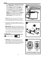
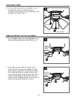
Turn off circuit breakers and wall switch to the fan 
supply line leads. (Fig. 1)


DANGER

: Failure to disconnect power supply 

prior to installation may result in serious injury or 
death.

 1. 

 2. 

ON

OFF

ON

OFF

1

7 ft.

min.

30 in.

min.

2

 3. 

7

Remove all mounting bracket nuts (K) and 
mounting bracket flat washers (P) from mounting 
bracket (B). (Fig. 3)

B

K

P

3

Check to make sure blades (H) will be at least 
30 in. from any obstruction and at least 7 ft. 
above the floor. (Fig. 2)

Содержание 317058

Страница 1: ...service department at 1 800 527 1292 8 30 a m 5 00 p m CST Monday Friday Harbor Breeze is a registered trademark of LF LLC All Rights Reserved ATTACH YOUR RECEIPT HERE Serial Number Purchase Date 1 I...

Страница 2: ...ANSI NFPA 70 1999 Hire a qualified electrician or consult a do it yourself wiring handbook available at Lowe s if you are unfamiliar with installing electrical wiring Make sure the installation site y...

Страница 3: ...this fan are designed to accept only one 12 gauge house wire and two lead wires from the fan If your house wire is larger than 12 gauge or there is more than one house wire to connect to the two fan...

Страница 4: ...to installation You can save installation time by deciding which options are best suited for your needs before beginning the steps outlined in this manual Your fan can be installed on a normal ceilin...

Страница 5: ...Kit Fitter 1 F Glass Shade 3 G Blade Arm 5 H Blade 5 I Candelabra Base Bulb 3 J Pull Chain Extension 2 K Mounting Bracket Nut 4 preassembled PART DESCRIPTION QUANTITY L Socket Ring 3 preassembled M M...

Страница 6: ...Required included 3 candelabra base 60 watt max bulbs DANGER When using an existing outlet box make sure the outlet box is securely attached to the building structure and can support the full weight o...

Страница 7: ...supply prior to installation may result in serious injury or death 1 2 ON OFF ON OFF 1 7 ft min 30 in min 2 3 7 Remove all mounting bracket nuts K and mounting bracket flat washers P from mounting br...

Страница 8: ...slot in the bar at the top of the motor assembly D onto the J hook on the mounting bracket B to support the fan during wiring Fig 6 Important Do not use the end of the bar on the motor assembly D wit...

Страница 9: ...connections as follows NOTE For each wire connection below use one of the wire connectors CC provided making sure to screw wire connector CC on in a clockwise direction 1A FAN AND LIGHT CONTROLLED BY...

Страница 10: ...ge dimmer switch not included to control fan speed will cause a loud humming noise from fan To reduce the risk of fire or electrical shock do NOT use a full range dimmer switch to control fan speed Fi...

Страница 11: ...other two motor housing mounting screws O and motor housing lock washers Q Slide motor housing A over motor assembly D aligning slotted holes in motor housing A with loosened motor housing mounting sc...

Страница 12: ...n Without Light Kit OPTIONAL on page 14 E Molex Connections FINAL INSTALLATION 4 R G N M Switch Housing Plate 4 5 5 R Locate motor screws M and lock washers N that were removed in Step 5 on page 8 Ins...

Страница 13: ...o replace bulbs please allow bulbs and glass shades to cool down before handling them 13 6 Switch Housing Plate Pull Chain Slot E Gently push wires and molex connections into switch housing plate Alig...

Страница 14: ...align with the reverse switch on the switch housing plate for the proper fit Re insert switch housing plate screws R that were just removed Use a Phillips screwdriver to secure all switch housing pla...

Страница 15: ...uded may be attached to fan Fig 3 J The pull chain on the switch housing plate which is inside the light kit fitter E has four positions to control fan speed One pull is HIGH two is MEDIUM three is LO...

Страница 16: ...ore moving the reverse switch 3 3A 3B 3A In warmer weather setting the reverse switch in the LEFT position will result in downward airflow creating a wind chill effect Fig 3A 3B In cooler weather sett...

Страница 17: ...tion 4 Wires not connected properly 1 Push switch firmly either to the right or to the left 2 Turn power on or check fuse 3 Turn power off Loosen motor housing A and check all connections 4 Check that...

Страница 18: ...ctive parts for the ceiling fan must be reported within the first year from the date of purchase For the balance of the warranty call our customer service department at 1 800 527 1292 for return autho...

Страница 19: ...page 1 A C H F G E B J K L P O Q R PART DESCRIPTION A Motor Housing B Mounting Bracket C Extra Switch Housing E Light Kit Fitter F Glass Shade G Blade Arm H Blade J Pull Chain Extension K Mounting Br...

Страница 20: ...Breeze es una marca registrada de LF LLC Todos los derechos reservados Preguntas problemas piezas faltantes Antes de volver a la tienda llame a nuestro Departamento de Servicio al Cliente al 1 800 527...

Страница 21: ...rizado con la instalaci n del cableado el ctrico contrate a un electricista calificado o consulte un manual de cableado disponible en Lowe s para hacerlo usted mismo Aseg rese de que el sitio de insta...

Страница 22: ...dise ados para soportar s lo un cable interior de calibre 12 y dos cables conductores del ventilador Si el cable interior es de un calibre superior a 12 o hay m s de un cable interior para conectar lo...

Страница 23: ...empo en la instalaci n si decide qu opciones se adaptan mejor a sus necesidades antes de comenzar a realizar los pasos detallados en este manual Su ventilador se puede instalar en techos normales unic...

Страница 24: ...rio 3 G Brazo para la paleta 5 H Paleta 5 I Bombilla de base 3 candelabro J Extensi n para la cadena 2 K Tuerca del soporte de 4 montaje preensamblada L Anillo de portal mpara 3 preensamblado M Tornil...

Страница 25: ...do para hacerlo usted mismo disponible en Lowe s y pinzas cortacables Bombillas requeridas se incluyen 3 bombillas de base candelabro de 60 vatios como m ximo PELIGRO Si utiliza una caja de salida exi...

Страница 26: ...o de electricidad antes de la instalaci n pueden producirse lesiones graves o la muerte Aseg rese de que las paletas H del ventilador quedar n a por lo menos 30 pulgadas 76 2 cm de cualquier obstrucci...

Страница 27: ...lado inferior del motor y gu rdelos para sujetar los brazos para las paletas G despu s Si se encuentran soportes de pl stico instalados con los tornillos del motor M y las arandelas de seguridad N de...

Страница 28: ...omienda que un electricista profesional determine el cableado adecuado 1A VENTILADOR Y LUZ CONTROLADOS POR CADENAS DE TIRO NEGRO BLANCO DE PUESTA A TIERRA VERDE DESNUDO BLANCO AZUL BLANCO DESDE EL VEN...

Страница 29: ...lador El conductor azul es el que proporciona alimentaci n al juego de luz El conductor blanco es el conductor com n para el ventilador y el kit de iluminaci n El conductor verde o desnudo es la puest...

Страница 30: ...uavemente los conductores y los conectores de cables CC hacia dentro de la caja de salida CC Conector de cables E3 x4 2 Art culos de ferreter a que se usaron 1 2 3 Regulador de intensidad Regulador de...

Страница 31: ...an con los agujeros con ranura en el borde superior del bastidor del motor A y afloje dichos tornillos del bastidor del motor O parcialmente Quite los otros dos tornillos del bastidor del motor O y la...

Страница 32: ...ntroduzca dos tornillos del motor M junto con las arandelas de seguridad N en uno de los brazos para la paleta G para sujetar el brazo para la paleta G al motor Apriete bien los tornillos del motor M...

Страница 33: ...uz opcional en la p gina 34 Delicadamente meta los cables y las conexiones tipo molex en la placa de la caja del interruptor Alinee la ranura para la cadena de encendido del ventilador con la cadena d...

Страница 34: ...adenas de encendido J provistas en uno de los paquetes de art culos de ferreter a a las cadenas de encendido para el ventilador y la luz o usar extensiones para cadena de encendido hechas a medida no...

Страница 35: ...s de la placa de la caja del interruptor R Fig 2 USO DEL VENTILADOR SIN EL JUEGO DE LUZ OPCIONAL Se puede fijar la extensi n para la cadena de encendido J provista en uno de los paquetes de art culos...

Страница 36: ...invierno sin notar una diferencia en su comodidad Nota Espere a que se detenga completamente el ventilador antes de usar el interruptor de reversa 3A En un clima m s caluroso el mover el interruptor d...

Страница 37: ...tro de electricidad para evitar descargas el ctricas PROBLEMA CAUSA POSIBLE ACCI N CORRECTIVA El ventilador no se mueve 1 El interruptor de reversa no est activado 2 No hay alimentaci n el ctrica o ha...

Страница 38: ...ron bien los tornillos de paletas AA 2 Instale los brazos para las paletas G de nuevo 3 Intercambie una paleta H con otra del lado contrario 4 Apague la electricidad Afloje el bastidor del motor A cui...

Страница 39: ...ciones clim ticas esta garant a no cubre ning n cambio en el acabado bronce ni por la oxidaci n marcas la decoloraci n la corrosi n ni el descascarillado del material Se conserva la belleza de un vent...

Страница 40: ...Q Arandela de seguridad del bastidor del motor R Tornillo de la placa de la caja del interruptor AA Tornillo de paleta BB Arandela de fibra para la paleta CC Conector de cables E3 40 LISTA DE PIEZAS...

Отзывы: