background image

12

WIRING


WARNING:

 To reduce the risk of fire, electrical shock or personal injury, wire connectors 

provided with this fan are designed to accept only one 12-gauge house wire and two lead wires 

from the fan. If your house wire is larger than 12-gauge and/or there is more than one house wire to 

connect to the two fan lead wires, consult an electrician for the proper size wire connectors to use.

CAUTION:

 Be sure the outlet box is properly grounded or that a Ground (Green or Bare) wire is present.

1.  


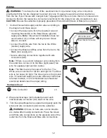
Connect household supply and fan wires according to 

the diagram and these steps:
• Connect the Green wire from the downrod (A) and 

mounting bracket (D) to the Bare/Green (ground) 

supply wire. 

Note:

 Closemount installation does not 

use downrod (A), so there will only be two Green 

wires to connect.  

• Connect the White wire from the fan to the White 

(neutral) supply wire. 

• Connect the Black and Blue wires from the fan to the 

Black (hot) supply wire.  

• Secure all wiring connections together with wire 

connectors (AA).

Note:

 If there is a second hot/power wire coming from 

the outlet box, connect it to the Blue (light power) fan 

wire for separate light and fan control.

Note:

 The Black wire is hot power for the fan. The 

White wire is common for the fan and light kit. The Blue 

wire is hot power for light. The Green wire is the ground 

wire. If household supply wires are different colors than 

referred to above, it is recommended a professional 

electrician determines the proper wiring.   


Hardware Used

AA

Wire Connector

x 3

2.  Wrap electrical tape (not included) around each 

individual wire connector (AA) down to the wire.

3.   Turn the spliced/taped wires upward and gently push the 

wires and wire connectors (AA) into the outlet box.


  WARNING:

 Ensure no bare wire or wire strands 

are visible after making connections. Place the Green 

and White wire connections on the opposite side of the 

outlet box from the Black and Blue wire connections.

1

2

3

AA

D

Black (Hot)

White (Neutral)

Bare/Green (Ground)

Black

Blue

White

Green

Содержание 1024423

Страница 1: ...our retailer call our customer service department at 1 800 643 0067 8 a m 8 p m EST Monday Sunday Harbor Breeze is a registered trademark of LF LLC All Rights Reserved VR20328 ITEM 1024423 1461048 2758997 MERRIMACK II CEILING FAN MODEL 41125 42073 42241 Español p 23 H arbor Bree z e H arbor Bree z e LISTED FOR DAMP LOCATION ...

Страница 2: ...rmation 5 Preparation 6 Initial Installation 7 Standard or Angle Mounting Instructions 9 Closemount Instructions 11 Wiring 12 Final Installation 13 Operating Instructions 18 Care and Maintenance 19 Troubleshooting 19 Limited Lifetime Warranty 21 Replacement Parts List 22 ...

Страница 3: ...Motor Assembly N 2 M Phillips Head Closemount Screws preassembled to Motor Assembly N 3 N Motor Assembly 1 O Fitter Plate Screw preassembled to Fitter Plate P 3 P Fitter Plate preassembled to Motor Assembly N 1 Q Light Kit 1 R Motor Screws preassembled to Motor Assembly N 10 S Light Pan Screw preassembled to Light Pan H 3 T Finial Cap preassembled to Light Kit Q 1 U Finial preassembled to Light Ki...

Страница 4: ...RE CONTENTS shown actual size Wire Connector Qty 3 1 extra Blade Screw Qty 15 1 extra Blade Washer Qty 15 1 extra Pull Chain Extension Qty 2 Motor Screw 1 extra AA BB CC DD XX H arbor Bree z e H arbor Bree z e ...

Страница 5: ... loud humming noise from the fan To reduce the risk of fire or electric shock do NOT use a full range dimmer switch to control the fan speed WARNING To reduce the risk of fire electric shock or personal injury mount the fan to an outlet box marked ACCEPTABLE FOR FAN SUPPORT and use the mounting screws provided with the outlet box Most outlet boxes commonly used for the support of lighting fixtures...

Страница 6: ...ff and on the user is encouraged to try to correct the interference by one or more of the following measures Reorient or relocate the receiving antenna Increase the separation between the equipment and receiver Connect the equipment into an outlet on a circuit different from that to which the receiver is connected Consult the dealer or an experienced radio TV technician for help Please note change...

Страница 7: ...e mounting is best suited for angled or vaulted ceilings A longer downrod is sometimes necessary to ensure proper blade clearance Note If using the angle mount check to ensure the ceiling angle is not steeper than 16 Closemount style mounting is more suitable for ceilings lower than 8 ft high Flushmount installation is not available for this item 2 Standard Mounting Flushmount Closemount Angle Mou...

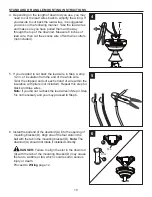
Страница 8: ...he outlet box CAUTION It is very important you use the proper hardware when installing the mounting bracket D as this will support the fan 6 Remove all 10 preassembled motor screws R and five preassembed motor blocks from the underside of the motor assembly N Discard the motor blocks but keep the motor screws R for later For Standard or Angle Mounting Instructions continue to page 9 For Closemount...

Страница 9: ...ke at the top of the motor assembly N 2 Insert the downrod A through the canopy E and yoke cover G Feed the wires from the motor assembly N through the downrod A 3 Slide the downrod A into the yoke of the motor assembly N align the holes then re install the downrod pin B and downrod clip C Secure with set screws L C B A A G N E 2 3 Yoke B A N C L L Yoke 1 ...

Страница 10: ...rom the end of the white wire Twist the stripped ends of each strand of wire within the insulation with pliers not included Repeat this step for black and blue wires Note If you did not cut back the lead wires in Step 4 Step 5 is not necessary and you may proceed to Step 6 6 Install the ball end of the downrod A into the opening of mounting bracket D Align one of the four slots in the ball with th...

Страница 11: ...ee Phillips head closemount screws M from the top of the motor assembly N Align the canopy E with the holes in the top of the motor assembly N then re install the Phillips head closemount screws M to secure the canopy E to the top of the motor assembly N 3 Raise the fan and place the canopy E on the hook on the mounting bracket D temporarily leaving hands free for the wiring process E F N M E 1 3 ...

Страница 12: ...rom the fan to the Black hot supply wire Secure all wiring connections together with wire connectors AA Note If there is a second hot power wire coming from the outlet box connect it to the Blue light power fan wire for separate light and fan control Note The Black wire is hot power for the fan The White wire is common for the fan and light kit The Blue wire is hot power for light The Green wire i...

Страница 13: ...4 page 8 Tighten all mounting bracket screws X securely 3 Partially insert the blade screws BB along with the blade washers CC through the blade K and into the blade arm J Tighten each blade screw BB with a Phillips screwdriver not included starting with the one in the middle Repeat this step for the remaining blades K and blade arms J Hardware Used BB Blade Screw x 15 Blade Washer x 15 K CC BB J ...

Страница 14: ... plate P and save Loosen but do not remove the other two fitter plate screws O Note Make sure to keep loose hardware separate to avoid confusion during installation 6 Align the two key slots in the light pan H with the loosened fitter plate screws O Place the light pan H over the two screws and turn the light pan H clockwise Then tighten the two fitter plate screws O Re install the fitter plate sc...

Страница 15: ...ackets 8 Connect the 9 pin connector from the fitter plate P to the 9 pin connector from the light kit Q 9 Align the two key slots in the light kit Q with the two previously loosened light pan screws S Place the light kit Q over the two screws and turn the light kit Q clockwise Re install the previously removed light pan screw S and tighten all three screws securely 7 8 9 H S Q S ...

Страница 16: ...glass globe I over the threaded rod on light kit Q Lift the finial cap T up until it is flush with the glass bowl I and secure with the finial U 12 Align the three grooves on the inside of the light frame W with the three raised bumps on the light kit Q Turn clockwise until it locks into place T U V T U I 11 12 W Q Bump Groove 10 ...

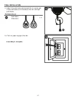
Страница 17: ...13 Attach the pull chain extensions DD or custom pull chain extensions not included to the fan and light pull chains Hardware Used DD Pull Chain Extension x 2 14 Turn on power supply to the fan Assembly is complete 13 14 DD H arbor Bree z e H arbor Bree z e ...

Страница 18: ...ler weather push the reverse switch to the right to display the snowflake icon which will result in upward airflow that can help move stagnant hot air off the ceiling area Important The reverse switch must be set either completely to the right or to the left for the fan to function correctly If the reverse switch is set in the middle position the fan will not operate Fig 1c 2 The fan pull chain ha...

Страница 19: ... sure the wall switch is turned on 3 Turn the power on or check the fuse breaker 4 Turn the power off and check all connections at the ceiling outlet box There is excessive wobbling 1 The blades and or blade arms are loose 2 The blades are unbalanced 3 The fan mounting is not secure 4 The fan is too close to the vaulted ceiling 5 The set screws on the motor assembly yoke is loose 1 Check and tight...

Страница 20: ...o not use a full range dimmer switch to control the fan speed 4 Ensure the outlet box is secured to the building structure 5 Ensure the mounting bracket is secured to the outlet box and that the screws are tight The fan operates correctly but the lights are not working 1 The bulbs are not installed correctly 2 The light kit wire plugs are not connected properly 3 There is a faulty wire connection ...

Страница 21: ...e to varying climate conditions this warranty does not cover any changes in plated finishes including rusting pitting corroding tarnishing or peeling Plated metals give their longest useful life when protected from varying weather conditions Any glass provided with this fan is not covered by the warranty Any replacement of defective parts from the ceiling fan must be reported within the first year...

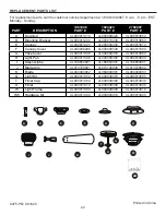
Страница 22: ...er 4L000008290 4L000009340 4L000011080 G Yoke Cover 4L000011330 4L000009350 4L000013880 H Light Pan 4L000011340 4L000009360 4L000013900 I Glass Globe 4L166850001 4L166850001 4L166850001 J Blade Arm 4L073720001 4L073720000 4L073720002 K Blade 4L084900002 4L084900001 4L084900003 Q Light Kit 4L000011350 4L000009370 4L000013890 T Finial Cap 4L000011360 4L000009380 4L000013930 U Finial 4L000011370 4L00...

Отзывы: