background image

2

Hangar 9 Pulse 125 ARF Assembly Manual

Table of Contents

Contents of Kit and Parts Layout ......................................2

Included Parts Listing .......................................................3

Using the Manual ..............................................................4

Important Information Regarding Warranty Information ..4

UltraCote® Covering Colors .............................................4

Before Starting Assembly .................................................4

Transmitter Requirements.................................................4

Radio Equipment Requirements .......................................4

Recommended Setup–2-Stroke Glow ...............................4

Recommended Setup–4-Stroke Glow ...............................4

Recommended Setup–4-Stroke Gas .................................4

Recommended Setup–Electric Power (EP) .......................4

Field Equipment Required .................................................4

Optional Field Equipment ..................................................4

Additional Required Tools .................................................5

Additional Required Adhesives .........................................5

FS One® ...........................................................................5

Rudder and Fin Preparation ..............................................5

Tail Installation ..................................................................7

Radio Installation ..............................................................8

Aileron Servo Installation ................................................11

Landing Gear and Wheel Installation ..............................13

Four-Stroke Engine Installation .......................................15

Two-Stroke Engine Installation .......................................19

Fuel Tank Installation ......................................................23

Cowling and Spinner Installation - Four-Stroke Engine ..25

Cowling and Spinner Installation - Two-Stroke Engine ...27

Electric Motor Installation ...............................................29

Cowling and Spinner Installation - Electric Motor...........31

Final Assembly ................................................................32

Center of Gravity .............................................................34

Control Throws ...............................................................34

Flight Preparations ..........................................................35

Safety Do’s and Don’ts for Pilots ....................................35

Daily Flight Checks ..........................................................35

Age Requirements ..........................................................36

Safety, Precautions and Warnings ..................................36

Warranty Information ......................................................36

CE Compliance Information for the European Union ......37

2009 Official Academy of  

Model Aeronautics Safety Code ................................38

Engine Mounting Template .............................................39

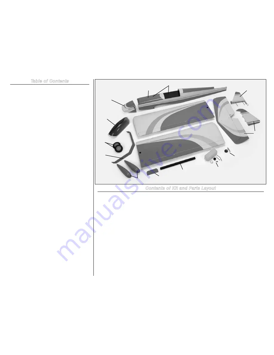
Replacement Parts

  1.  HAN517001  

Fuselage with Hatch

  2.  HAN517002  

Fuselage Hatch

  3.  HAN517003  

Left Wing Panel

  4.  HAN517004  

Right Wing Panel

  5.  HAN517005  

Horizontal and Vertical Stabilizer

  6.  HAN517006  

Canopy

  7.  HAN517007  

Cowl

  8.  HAN517008  

Landing Gear, with Axles

  9.  HAN517010  

Wing Tube

 10.  HAN517011  

Wheelpants (2)

 11.  HAN517012  

Main Wheels

 12.  HAN517015  

Fuel Tank

 13.  HAN517017  

Tailwheel Assembly

 14.  HAN517018  

Wing Bolt Plate

Items not shown:

HAN517009 


Landing Gear Axles

HAN517013 


Engine Mount

HAN517014 


EP Motor Mount

HAN517016 


Hardware Package

HAN517019 


Wing Mounting Nylon Bolts

Contents of Kit and Parts Layout

1

2

3

4

5

5

6

7

8

9

14

10

11

12

13

Содержание Pulse 125

Страница 1: ... 5 in 159 cm Wing Area 1050 sq in 68 0 sq dm Weight 8 2 9 5 lb 3 7 4 3 kg Engine Size 61 1 20 2 stroke 90 1 25 4 stroke Motor Size 90 110 brushless outrunner Motor Radio 4 channels or more w 5 servos 4 w electric option Pulse 125 ARF Assembly Manual ...

Страница 2: ...wo Stroke Engine 27 Electric Motor Installation 29 Cowling and Spinner Installation Electric Motor 31 Final Assembly 32 Center of Gravity 34 Control Throws 34 Flight Preparations 35 Safety Do s and Don ts for Pilots 35 Daily Flight Checks 35 Age Requirements 36 Safety Precautions and Warnings 36 Warranty Information 36 CE Compliance Information for the European Union 37 2009 Official Academy of Mo...

Страница 3: ... x 50mm aluminum tube 2 3mm x 70mm aluminum tube 1 Rubber stopper 1 Self tapping screw 1 Silicon tube 1 Nylon stopper piece 2 10mm x 10mm x 110mm tank brace 1 Wing and Tail Hardware 5 16 x 2 inch dowel with aluminum sleeve 2 6mm x 40mm nylon wing bolt 2 Wing bolts 3mm washer 2 Tail attachment 3mm nylon lock nut 2 Tail attachment Motor Mount Nylon motor mount 2 75mm aluminum standoff 4 4mm x 25mm s...

Страница 4: ...eceiver SPM6600 Spektrum DX7 with receiver SPM2710 JR Systems X9303 2 4GHz with receiver JRP2915 Radio Equipment Requirements The following items are recommended when installing the receiver in your aircraft AR7000 7 Channel Receiver SPM6070 DS821 Digital Sport Servo 5 JRPS821 Note Only 4 servos required for EP version 9 inch Servo Extension 2 JRPA097 3 inch Servo Extension 2 JSP98100 or Y harness...

Страница 5: ...aircraft You get incredibly advanced aerodynamic modeling that simulates every possible aspect of real world flight The first Hangar Pack HANS4010 will add even more aircraft to FS One This latest edition includes ten new planes and helis from your favorite brands including Hangar 9 E flite and Align You ll be able to fly aircraft that are only available on FS One such as the T REX Blade CX2 Blade...

Страница 6: ... Step 5 Mix a small amount of 30 minute epoxy Apply the epoxy to both the tail gear wire where it enters the rudder and to the hole in the rudder Note Use a paper towel and rubbing alcohol to remove any excess epoxy before it cures Excess epoxy could cause the rudder and fin to bind and increase the load on the rudder servo Step 6 The rudder and fin can now be joined together While the epoxy cures...

Страница 7: ...ator stabilizer assembly 3mm washer 2 3mm locknut 2 Tools and Adhesives Nut driver 5 5mm Thin CA Important Check and break in the elevator hinges before starting this section of the manual Apply thin CA to any loose hinges Step 1 Position the stabilizer on the stabilizer saddle at the rear of the fuselage Step 2 Insert the threaded rods from the fin through the holes in the stabilizer and into the...

Страница 8: ...er 1 4 inch 6mm foam Y harness Elevator linkage wire 27 5 inch 698mm Rudder linkage wire 28 5 inch 724mm Tools and Adhesives Phillips screwdriver 1 2 Side cutters Straight edge Thin CA Pin drill Drill bit 5 64 inch 2mm Step 1 Slide the hatch on the fuselage forward to disengage the magnets at the rear of the hatch Lift the hatch up at the rear and remove it from the fuselage Step 2 Use a 1 Phillip...

Страница 9: ...eiver battery in foam and secure it in position using a hook and loop strap not included Step 7 Plug the rudder and elevator servo leads in the correct ports of your receiver Also plug the aileron Y harness and lead from the switch harness at this time Step 8 Wrap the receiver in foam and secure it in position as shown Note The remote receiver will be mounted later in the manual Its location will ...

Страница 10: ...the center of the servo horn for the pushrod wires Step 12 Remove the horns from the rudder servo and use side cutters to trim the arm from the horn that will not be used Note Removing the excess arm will help in preventing interference between the arm and other components inside the fuselage Step 13 Insert the Z bend from the 281 2 inch 724mm pushod in the hole enlarged earlier Step 14 Slide the ...

Страница 11: ...at Steps 12 through 17 to install the 27 5 inch 698mm linkage wire for the elevator Attach the clevis to the center hold on the elevator control horn Aileron Servo Installation Required Parts Wing panel right and left Metal clevis 2 Clevis retainer 2 2mm nut 2 Wing dowel 2 Servo with hardware 2 9 inch 228mm servo entension 2 Aileron linkage wire 3 5 inch 90mm 2 Tools and Adhesives Thin CA Mixing c...

Страница 12: ...m the wing Tie the end around the servo extension Step 5 Use the string to pull the servo lead through the wing and out the hole as shown Step 6 Secure the servo in the wing using the screws included with the servo Make sure the output of the servo faces the aileron Step 7 Remove the stock servo horns from the servo Center the servo using the radio system Use a 180 degree servo horn on the servo Y...

Страница 13: ... 30 minute epoxy to glue the wing dowel in the leading edge of the wing Remove any excess epoxy using a paper towel soaked in rubbing alcohol Step 12 Repeat Steps 1 through 12 to prepare the opposite wing panel Landing Gear and Wheel Installation Required Parts Fuselage Aluminum landing gear Wheel axle with nut 2 Main wheel 2 Tail wheel Wheel pant right and left 3mm x 8mm button head screw 4 2mm w...

Страница 14: ...the collars more secure on the axle Step 4 Position one of the wheel collars 3 8 inch 9 5mm from the edge of the gear as shown Tighten the setscrew to secure the collar to the axle Note Always use threadlock on metal to metal fasteners to prevent them from vibrating loose Step 5 Place the wheel on the axle then use another wheel collar to secure the wheel Make sure the collar is not too tight agai...

Страница 15: ...the tail wheel on the tail gear wire Note Always use threadlock on metal to metal fasteners to prevent them from vibrating loose Four Stroke Engine Installation Required Parts Fuselage 4mm washer 8 4mm locknut 4 Throttle pushrod with clevis Brass pushrod connector with backplate 4mm x 25mm socket head bolt 8 Engine mount rail right and left Plywood engine mount template Tools and Adhesives Drill L...

Страница 16: ...Step 3 Remove the template and use a 5 32 inch 4mm drill bit to enlarge the four holes drilled in the previous step Step 4 Use four 4mm x 25mm socket head screws and four 4mm washers to secure the nylon mounts to the firewall Note the positioning of the mounts as shown in the photos Step 5 Position the engine on the mount so the front face of the driver washer is 51 2 inches 140mm forward of the f...

Страница 17: ...n move freely Step 9 Use a drill and a 5 32 inch 4mm drill bit to drill the four holes through the mount to secure the engine Hint It is suggested to use a drill press to drill these holes This will guarantee they are aligned straight in the mount Step 10 Check the direction of the carburetor in relationship to the engine If it does not look like the position in the photo below follow the instruct...

Страница 18: ... screws four 4mm washers and four 4mm nylon locknuts The washers will be on the bottom side of the mount between the locknut and nylon mount Step 14 Thread a servo mounting screw into each of the holes in the radio tray This will cut the threads for the screws in preparation of the next step Step 15 Place 2 3 drops of thin CA in each hole to harden the surrounding wood This harder surface will mak...

Страница 19: ...e setscrew in the pushrod connector to secure the wire to the carburetor arm Use side cutters to trim any excess wire extending beyond the connector Note Always use threadlock on metal to metal fasteners to prevent them from vibrating loose Two Stroke Engine Installation Required Parts Fuselage 4mm washer 8 4mm locknut 4 Throttle pushrod with clevis Brass pushrod connector with backplate 4mm x 25m...

Страница 20: ...Step 3 Remove the template and use a 5 32 inch 4mm drill bit to enlarge the four holes drilled in the previous step Step 4 Use four 4mm x 25mm socket head screws and four 4mm washers to secure the nylon mounts to the firewall Note the positioning of the mounts as shown in the photos Step 5 Position the engine on the mount so the front face of the driver washer is 51 2 inches 140mm forward of the f...

Страница 21: ...e to the mount using four 4mm x 25mm socket head screws four 4mm washers and four 4mm nylon locknuts The washers will be on the bottom side of the mount between the locknut and nylon mount Step 9 Slide the throttle pushrod in the pushrod tube Bend the pushrod so the clevis can be connected to the innermost hole of the carburetor arm Slide the clevis retainer over the forks of the clevis so it won ...

Страница 22: ...ay using the screws provided with the servo Step 13 Remove the servo horn from the servo Use a pin drill and 5 64 inch 1 5mm drill bit to enlarge the hole that is 1 2 inch 13mm from the center of the center of the horn Step 14 Use side cutters to remove any excess arms from the servo horn so they don t interfere with the operation of the throttle Step 15 Insert the brass pushrod connector in the h...

Страница 23: ...be straight Copper fuel tube bent Fuel tank stopper Steel clunk Clunk fuel line Stopper clamp 2mm locknut Nylon tie wrap Fuel tubing gas or nitro 2mm x 12mm machine screw 1 4 inch 6mm foam rubber Tools and Adhesives Phillips screwdriver 1 Pliers Side cutter Double sided tape Hobby knife with 11 blade Important Two types of fuel tubing have been included for your model One is for use with nitrometh...

Страница 24: ...ve the stopper and shorten the fuel tube slightly check and repeat until it can move freely inside the tank Step 4 Use a 2mm x 12mm machine screw and 2mm locknut to secure the stopper clamp around the stopper This will keep the stopper secure on the neck of the fuel tank Step 5 Attach the fuel line to the clunk and vent lines of the tank The line will be trimmed when it is connected to the engine ...

Страница 25: ...er on the side of the fuselage opposite the throttle servo The antenna wires should face up and down for the best reception of your radio system Cowling and Spinner Installation Four Stroke Engine Required Parts Fuselage Cowling Spinner backplate Spinner cone 3mm x 10mm self tapping screw 2 3mm x 8mm button head screw 4 Tools and Adhesives Cardstock Low tack tape Felt tipped pen Hobby scissors Phi...

Страница 26: ...to the carburetor Step 5 Remove the cowl and trim it using the lines made in the previous step With the engine back on the firewall check to make sure the cowl will fit over the engine Take your time trimming the cowl to achieve the best fit Use a rotary tool and sanding drum to smooth any rough edges around the engine Step 6 Use the instructions provided with the engine to attach the muffler Trim...

Страница 27: ...rts Fuselage Cowling Spinner backplate Spinner cone 3mm x 10mm self tapping screw 2 3mm x 8mm button head screw 4 Tools and Adhesives Cardstock Low tack tape Felt tipped pen Hobby scissors Phillips screwdriver 2 Rotary tool with sanding drum Hex wrench or ball driver 2mm Step 1 Cut a piece of cardstock to fit around the engine as shown This will be the template for trimming your cowling Step 2 Rem...

Страница 28: ... Use a rotary tool and sanding drum to smooth any rough edges around the engine Step 6 Use the instructions provided with the engine to attach the muffler Trim and connect the pressure line from the fuel tank to the muffler Step 7 Slide the spinner backplate on the engine shaft Step 8 Slide the propeller on the engine shaft Use the hardware provided with the engine to secure the propeller The smal...

Страница 29: ...ife to remove the covering on the bottom of the fuselage to allow air to pass though the fuselage Use a covering iron to seal the edges around the opening so the covering does not come loose Step 2 Slide the hatch on the fuselage forward to disengage the magnets at the rear of the hatch Lift the hatch up at the rear and remove it from the fuselage Step 3 Use a hobby knife and 11 blade to remove th...

Страница 30: ... four 4mm x 25mm socket head screws and four 4mm washers to attach the four aluminum motor standoffs to the firewall Note Always use threadlock on metal to metal fasteners to prevent them from vibrating loose Step 8 Prepare the motor by installing the X mount and propeller adapter Note Always use threadlock on metal to metal fasteners to prevent them from vibrating loose Step 9 Secure the speed co...

Страница 31: ...nd battery tray to keep them from sliding in the fuselage Cowling and Spinner Installation Electric Motor Required Parts Fuselage Cowling Spinner backplate Spinner cone 3mm x 10mm self tapping screw 2 3mm x 8mm button head screw 4 Tools and Adhesives Tapered reamer Phillips screwdriver 2 Hex wrench or ball driver 2mm Rotary tool and sanding drum Step 1 Use a rotary tool and sanding drum to remove ...

Страница 32: ...tions that could damage the airframe or motor bearings Step 6 Secure the propeller using a box wrench and the hardware from the adapter Step 7 Secure the spinner cone to the backplate using two 3mm x 10mm self tapping screws Final Assembly Required Parts Fuselage Canopy Wing panel left and right Wing bolt plate Aluminum wing tube 6mm x 40mm nylon wing bolt 2 Tools and Adhesives Canopy glue Medium ...

Страница 33: ...nels will fit tightly together Step 4 Connect the leads from the aileron servos into the leads coming from the aileron port of the receiver Step 5 Place the wing on the bottom of the fuselage Slide the wing forward so the wing dowels go into the hole in the fuselage Step 6 Place the wing bolt plate in position The rounded edges of the plate face to the front of the aircraft Step 7 Secure the wing ...

Страница 34: ...rudder should also move right Reverse the direction of the servo at the transmitter if necessary Step 2 Check the movement of the elevator with the radio system Moving the elevator stick toward the bottom of the transmitter will make the airplane elevator move up Step 3 Check the movement of the ailerons with the radio system Moving the aileron stick right will make the right aileron move up and t...

Страница 35: ... of control of your aircraft Strong winds can cause similar problems Do not point the transmitter antenna directly toward the model The radiation pattern from the tip of the antenna is inherently low Do not take chances If at any time during flight you observe any erratic or abnormal operation land immediately and do not resume flight until the cause of the problem has been ascertained and correct...

Страница 36: ...zon s sole obligation hereunder shall be that Horizon will at its option i repair or ii replace any Product determined by Horizon to be defective In the event of a defect these are the Purchaser s exclusive remedies Horizon reserves the right to inspect any and all equipment involved in a warranty claim Repair or replacement decisions are at the sole discretion of Horizon This warranty does not co...

Страница 37: ...as Visa MasterCard American Express and Discover cards If you choose to pay by credit card please include your credit card number and expiration date Any repair left unpaid or unclaimed after 90 days will be considered abandoned and will be disposed of accordingly Please note non warranty repair is only available on electronics and model engines United States Electronics and engines requiring insp...

Страница 38: ...en and where required by rule helmets must be properly worn and fastened They must be OSHA DOT ANSI SNELL or NOCSAE approved or comply with comparable standards RADIO CONTROL 1 All model flying shall be conducted in a manner to avoid over flight of unprotected people 2 I will have completed a successful radio equipment ground range check before the first flight of a new or repaired model aircraft ...

Страница 39: ...39 Hangar 9 Pulse 125 ARF Assembly Manual SAITO 1 25 EVOLUTION 1 20 E FLITE POWER 110 3 69 inch 91 73mm 3 69 inch 97 73mm Engine Mounting Template ...

Страница 40: ...15369 Printed 07 09 2009 Horizon Hobby Inc 4105 Fieldstone Road Champaign Illinois 61822 USA 877 504 0233 horizonhobby com Hangar 9 com ...

Отзывы: