background image

48

Hangar 9 Funtana 125 ARF Assembly Manual

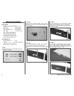
Aileron Servo Installation

Required Parts

Wing panel assembly (right and left)
Ball end (2) 

3mm washer (4)

Clevis end (2) 

4-40 locknut (2)

Servo with hardware (2) 

2mm locknut (2)

2mm locknut 

1

1

/

2

-inch servo arm

2mm x 12mm machine screw (2)
Servo extension, 6-inch (152mm)
4-40 x 1/2-inch hex head bolt (2)
Threaded pushrod, 6-inch (152mm)
3mm x 12mm hex head bolt (4)

Tools and Adhesives

Phillips screwdriver: #1 

Ruler

Thin CA 

String or dental floss

Hex wrench: 3/32-inch or 2.5mm
Nut driver: 4mm, 1/4-inch or 5.5mm


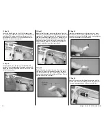
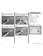
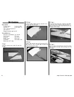
Step 1

Locate the items necessary to install the aileron servo 

included with your model.




Step 2

Remove the servo horn from the aileron servo. Use string 

or dental floss to secure a 6-inch (152mm) extension to the 

aileron servo lead.




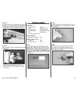
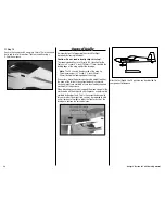
Step 3

Use a #1 Phillips screwdriver to thread a servo mounting 

screw into each of the four holes in the aileron servo 

mounting plate. This will cut threads in the wood for the next 

step.




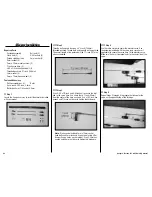
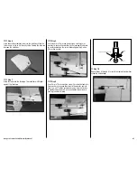
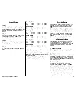
Step 4

Place 2–3 drops of thin CA into each of the holes to harden 

the threads cut in the previous step. This will make the 

screws more secure when installed and prevent them from 

vibrating loose in flight.




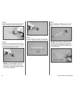
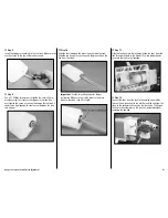
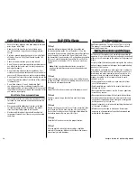
Step 5

Guide the aileron servo lead through the wing. Secure the 

servo in the wing using a #1 Phillips screwdriver and the 

screws included with the servo. Make sure the output of the 

servo faces toward the aileron as shown.

Содержание Funtana 125

Страница 1: ... in 1745 mm Wing Area 1108 sq in 71 5 sq dm Weight 8 0 8 5 lb 3 63 4 03 kg Engine Size 61 1 20 2 stroke 90 1 25 4 stroke Motor Size 90 110 brushless outrunner Motor Radio 4 channels or more w 6 servos 5 w electric option Funtana 125 ARF Assembly Manual ...

Страница 2: ...n 48 Wing Installation 50 Center of Gravity 52 Control Throws 53 Rates and Expos 53 Flight Preparations 53 Safety Do s and Don ts for Pilots 54 Daily Flight Checks 54 Age Requirements 54 Safety Precautions and Warnings 54 Warranty Information 55 CE Compliance Information for the European Union 56 2009 Official Academy of Model Aeronautics Safety Code 56 Engine Mounting Template Saito FG20 59 Repla...

Страница 3: ...t 5 rudder elevator and ailerons 2mm x 16mm sheet metal screws 15 control horn attachment 2mm x 12mm phillips machine screw 5 horn brackets to nylon clevis 2mm silver flat washers 10 horn brackets to nylon clevis 2mm nylocks 5 horn brackets to nylon clevis 4mm wheel axles 2 2mm x 16mm sheet metal screws 2 tail wheel to fuselage 4mm lock nuts 6 wheel axles 2 engine to engine mount 4 4mm wheel colla...

Страница 4: ...erate correctly without the use of a computer radio Two identical rotation servos can be used but you will need to use a computer radio or a JR MatchBox to operate the servos in the correct direction for the elevator The following items are recommended when installing the receiver in your aircraft AR7000 7 Channel Receiver SPM6070 DS9411 Digital Mid MG Servo 4 JRPSDS9411 DS9411R Digital Mid MG Rev...

Страница 5: ...ry 5000mAh 4 Cell 4S 14 8V 2 THP50004SP30 Tru Turn 23 4 inch Spinner TRU2502BW 24 inch 610mm Servo Extension JSP98040 Field Equipment Required Fuel 15 recommended Propeller Long Reach Glow Plug Wrench HAN2510 Metered Glow Driver w Ni Cd Charger HAN7101 2 Cycle Sport Plug EVOGP1 Manual Fuel Pump HAN118 Optional Field Equipment Hinge gap sealing tape or UltraCote covering white or clear Selfstick we...

Страница 6: ...s with the Hangar Pack you still get all the same great features that you did with the original aircraft HANS2008 HANS4010 Radio Installation Required Parts Fuselage Plywood receiver tray Servo with hardware 3 Rudder 1 Elevator 2 Receiver Switch harness with hardware 3 inch 76mm servo extension 2 ailerons 18 inch 457mm servo extension rudder 18 inch 457mm servo extension 2 elevator 2mm x 12mm self...

Страница 7: ...ion so you can differentiate the rudder lead from the elevator leads later in this section of the manual Step 6 Mount the servo using the four screws that were included with the servo Tighten the screws using a 1 Phillips screwdriver Step 7 Repeat Steps 3 through 6 to install the two elevator servos Make sure the output of the servos face to the rear of the fuselage Step 8 Use a hobby knife with a...

Страница 8: ... Phillips screwdriver to tighten the screws Make sure to harden the holes for the screws by placing 2 3 drops of thin CA in each hole before installing the screws Hint Secure any excess servo extensions using tie wraps or clear tape to clean up the radio installation Step 13 Use hook and loop tape or two sided tape to secure the remote receiver inside the fuselage The remote receiver should be as ...

Страница 9: ...Plug the throttle servo into the receiver at this time Hinging the Elevators and Ailerons Required Parts Elevator 2 CA hinge 14 Stabilizer right and left Wing panel right and left Aileron right and left Control horn 4 Control horn end 4 2mm x 16mm self tapping screw 12 Tools and Adhesives Ruler Felt tipped pen Phillips screwdriver 1 Drill Drill bit 1 16 inch 1 5mm Low tack tape Pin vise Thin CA Ho...

Страница 10: ...a felt tipped pen to transfer the location for the three mounting holes on the elevator Step 4 Use a drill and 1 16 inch 1 5mm drill bit to drill the holes for the horn mounting screws Drill the holes 5 8 inch 16mm deep Hint Wrap a piece of tape around the drill bit so you can drill the depth of the holes accurately The tape will indicate when you reach the proper depth Step 5 Use a 1 Phillips scr...

Страница 11: ... to wick into making a better bond between the hinge and surrounding wood Step 10 Place a T pin in the center of each of the three hinges that will be used to hinge the elevator to the stabilizer The T pins will center the hinge evenly in both the elevator and stabilizer Step 11 Slide the hinges into the elevator Step 12 Slide the elevator in position against the stabilizer Make sure all three hin...

Страница 12: ...ecure If not reapply CA to the hinge that is not secure Important Sealing the hinge gap is necessary on models that have large control surfaces and use large control throws Not sealing the hinge gap can lead to flutter of the control surface and could result in the loss of your aircraft Make sure to seal the hinge gap at this time Step 17 Use clear tape clear covering or white covering to seal the...

Страница 13: ...he location for the three mounting holes on the aileron Step 22 Use a drill and 1 16 inch 1 5mm drill bit to drill the holes for the horn mounting screws Drill the holes 5 8 inch 16mm deep Hint Wrap a piece of tape around the drill bit so you can drill the depth of the holes accurately The tape will indicate when you reach the proper depth Step 23 Use a 1 Phillips screwdriver to thread a 2mm x 16m...

Страница 14: ...that will be used to hinge the aileron to the wing The T pins will center the hinge evenly in both the aileron and wing Step 29 Slide the hinges into the aileron Step 30 Slide the aileron in position against the wing Make sure all four hinges go into the slots in the wing Step 31 Position the aileron so it is set back 1 32 inch 5mm from the wing tip This will be necessary to prevent the aileron fr...

Страница 15: ...secure If not reapply CA to the hinge that is not secure Important Sealing the hinge gap is necessary on models that have large control surfaces and use large control throws Not sealing the hinge gap can lead to flutter of the control surface and could result in the loss of your aircraft Make sure to seal the hinge gap at this time Step 35 Use clear tape clear covering or white covering to seal th...

Страница 16: ...cluded with your model Step 2 Measure up from the bottom of the rudder 5 8 inch 16mm and mark the rudder using a felt tipped pen Step 3 Use a pin vise and 3 32 inch 2 5mm drill bit to drill a hole that is 1 inch 25mm deep in the rudder at the mark made in the previous step This hole must be at the high point of the hinge line as shown Step 4 Carefully use a hobby knife and 11 blade to cut a notch ...

Страница 17: ...nt of 30 minute epoxy Apply the epoxy to the wire as well as the hole and notch in the rudder Hint Use a toothpick to get the epoxy into the hole in the rudder Step 9 Slide the tail wheel wire into the hole Use a paper towel and rubbing alcohol to remove any excess epoxy Use low tack tape to hold the wire in position until the epoxy fully cures Step 10 Position the control horn on the rudder The f...

Страница 18: ...t threads in the wood Step 13 Place 2 3 drops of thin CA into each hole This will harden the threads and prevent the screws from pulling loose Step 14 Thread a control horn end on the control horn until the top edge of the end is 1 inch 25mm from the base of the horn as shown Step 15 Secure the control horn to the rudder using three 2mm x 16mm self tapping screws and a 1 Phillips screwdriver Step ...

Страница 19: ...ely without the balance tab rubbing at the top of the fin Also make sure the rudder is offset slightly from the bottom of the fuselage so the tail wheel bracket when installed will not interfere with the operation of the rudder Remove the T pins from the hinges Make sure there is as little gap between the rudder and fuselage as possible Step 21 Use thin CA to saturate each of the three hinges on b...

Страница 20: ... a few dozen times to break in the hinges Step 24 Use a felt tipped pen to mark the locations for the two screws that will secure the tail wheel bracket to the fuselage Step 25 Move the bracket out of the way and use a drill with a 1 16 inch 1 5mm drill bit to drill the two holes for the screws Step 26 Place 2 3 drops of thin CA into each hole to harden the surrounding wood This will keep the scre...

Страница 21: ...ew 4mm 2 Tools and Adhesives Light oil Flat file Hex wrench 1 5mm 3mm Threadlock Nut driver 7mm Open end wrench 10mm Drill bit 5 32 inch 4mm Drill Felt tipped pen Ruler Threadlock Step 1 Locate the items necessary to attach the landing gear that are included with your model Step 2 Slide one of the 1 16 inch wheel collars on the tail gear wire Use a 1 5mm hex wrench to tighten the setscrew and secu...

Страница 22: ...n t vibrate loose Tighten the bolts using a 3mm hex wrench Step 6 Use the edge of a flat file to make two flat areas on the bottom of the axle against the mounting flange and at the end of the axle Step 7 Slide one of the 4mm wheel collars to the axle against the mounting flange of the axle as shown Tighten the setscrew using a 1 5mm hex wrench Use threadlock on the setscrew so it doesn t vibrate ...

Страница 23: ...nd wrench Step 13 Repeat Steps 6 through 12 to prepare and install the remaining wheel and wheel pant Step 14 Place the fuselage on your work surface so the main and tail wheels are resting on the same surface Make sure the wheel pant is fully pressed against the axle Position the wheel pant so the trailing edge tip of the wheel pant is 15 8 inch 41mm from the work surface as shown Step 15 Use a f...

Страница 24: ...Plywood battery tray Hook and loop strap 5 Tie wrap 3 Motor battery 2 4mm x 15mm hex head bolts 8 24 inch 610mm servo extension Tools and Adhesives Hex wrench 2 5mm 3mm Soldering iron Solder Ruler 30 minute epoxy Mixing cup Mixing stick Paper towel Rubbing alcohol Clear tape Threadlock Step 1 Locate the items necessary to install the electric motor included with your model Step 2 Use a 2 5mm hex w...

Страница 25: ...older any necessary connectors to the speed control at this time Step 7 Attach the speed control to the side of the motor box using two sided tape and tie wraps Connect the appropriate leads from the speed control to the motor Make sure the leads will not interfere with the operation of the motor Step 8 Secure a 24 inch 610mm servo extension to the lead from the speed control using string or denta...

Страница 26: ...acts the fuselage and to the wing tube Allow the epoxy to fully cure before moving to the next step Hint You can leave the tray loose for now The receiver battery and motor batteries can be repositioned to adjust the CG if needed If the receiver battery requires moving it will be easier to remove the battery tray to move the receiver pack Once the tray is glued in it will be difficult to access th...

Страница 27: ...lips screwdriver 1 Felt tipped pen Ruler Drill bit 1 16 inch 1 5mm 9 64 inch 3 5mm 5 32 inch 4mm Step 1 Locate the items necessary to install the engine included with your model Step 2 Use four 4mm x 25mm hex head bolts and four 4mm washers to attach the engine mount rails to the firewall Tighten the screws using a 3mm hex wrench after applying threadlock to each of the screws Step 3 Position the ...

Страница 28: ...l for the throttle pushrod tube Step 8 Use medium sandpaper to sand a 1 4 inch 6mm section of the 161 2 inch 420mm throttle pushrod tube at positions that are 2 inch 51mm and 61 2 inch 165mm from one end of the tube Step 9 Slide the pushrod tube in the firewall and guide it through the fuel tank mount and alongside the receiver battery The amount of tube forward of the firewall should measure 17 8...

Страница 29: ...ep 14 Use the radio to move the servo to the closed throttle position Close the carburetor at the engine and use a felt tipped pen to mark the pushrod where it crosses the outer hole of the servo horn Step 15 Move the throttle servo to open using the radio Open the carburetor at the engine and note where the line crosses the servo horn If it does not line up to the outer hole you may need to use a...

Страница 30: ...e screw that secures the throttle pushrod wire Make sure to use threadlock on the screw so it does not vibrate loose Step 20 Attach the muffler to the engine using the hardware provided with the muffler 4 Stroke Glow Engine Installation Required Parts Fuselage assembly Pushrod connector 2mm washer 2mm knurled nut 4mm locknut 4 4mm washer 8 Throttle pushrod tube 161 2 inch 420mm Throttle pushrod wi...

Страница 31: ... instructions provided with the engine Also make sure the carburetor arm is facing to the top of the engine Step 4 Position the engine so the drive washer is 51 4 inch 133mm forward of the firewall Step 5 Use a pencil to transfer the locations for the engine mounting bolts to the engine mount rails Step 6 Use a pencil to mark the location for the throttle pushrod tube Step 7 Remove the engine from...

Страница 32: ...nd 41 2 inch 115mm from one end of the tube Step 10 Slide the pushrod tube in the firewall and guide it through the fuel tank mount and alongside the receiver battery The amount of tube forward of the firewall should measure 1 16 inch 1 5mm Use medium CA to glue the tube to the firewall and the fuel tank mount Step 11 Use side cutters to trim the tube at the forward edge of the throttle servo Step...

Страница 33: ...le position Close the carburetor at the engine and use a felt tipped pen to mark the pushrod where it crosses the outer hole of the servo horn Step 16 Move the throttle servo to open using the radio Open the carburetor at the engine and note where the line crosses the servo horn If it does not line up to the outer hole you may need to use a different length servo arm a different hole in the servo ...

Страница 34: ... to use threadlock on the screw so it does not vibrate loose Step 21 Attach the muffler to the engine using the hardware provided with the muffler Note We used a 90 degree adapter to center the muffler to reduce the amount of cowling that will need to be removed 4 Stroke Gas Engine Installation Required Parts Fuselage assembly Pushrod connector 2mm washer 2mm knurled nut 4mm locknut 4 4mm washer 8...

Страница 35: ...ry to allow the carburetor to see true air pressure Without this hole the engine will not operate correctly Step 6 Attach the mount to the firewall using the hardware provided with the mount Use the longer 4mm x 20mm hex head bolts four 4mm star washers and four 4mm blind nuts for this purpose Use a 3mm hex wrench and threadlock on the screws Step 7 Use a 7 32 inch 5 5mm drill bit to drill four ho...

Страница 36: ...rod tube at positions that are at one end of the tube and 41 2 inch 115mm from one end of the tube Step 11 Slide the pushrod tube in the firewall and guide it through the fuel tank mount and alongside the receiver battery The amount of tube forward of the firewall should measure 1 16 inch 1 5mm Use medium CA to glue the tube to the firewall and the fuel tank mount Step 12 Use side cutters to trim ...

Страница 37: ...he engine box Connect the lead from the module to the switch harness at this time as well Step 16 Connect the Z bend in the 193 8 inch 492mm throttle pushrod to the outer hole of the carburetor arm as shown Step 17 Slide the throttle pushrod wire into the tube Position the engine between the mounts Use the four 4mm x 15mm hex head bolts and four 4mm star washers to secure the engine to the mount M...

Страница 38: ...nt length servo arm a different hole in the servo horn or reposition the linkage at the carburetor Adjusting the throws at the radio can also be used when using a computer radio but it is best to set the throw as closely as possible using mechanical methods Step 22 Remove the servo horn from the servo Use a pin vise and 5 64 inch 2mm drill bit to enlarge the hole in the servo horn that worked best...

Страница 39: ... band 2 3mm x 20mm machine screw Tools and Adhesives Hobby knife with 11 blade Ruler Optional Accessories for Gas Soldering iron Solder Music wire 1 32 inch Pliers Step 1 Locate the items necessary to assemble and install the fuel tank in your model Two sets of fuels lines have been included with your model The three yellow lines are for use with gas engines while the red green and clear tubes are...

Страница 40: ...ed to use solder and a soldering iron to create a small barb for the fuel line This is necessary as the tubing will need to be wired on to prevent it from sliding loose Step 6 Cut a piece of fuel tubing to a length of 23 16 inch 56mm Use the clear tubing for glow and the yellow tubing for gas Step 7 Slide the fuel tubing on the straight piece of brass tubing The clunk will be placed on the opposit...

Страница 41: ...the tank Slide the red line on the vent line and the green line on the line from the clunk Important Use the two yellow tubes for the gas installation Make sure to wire the tubes to the brass tubes so they don t slip off in flight Step 11 Slide the fuel tank into the fuselage Guide the lines from the tank through the hole in the firewall Use two rubber bands to secure the tank in the fuselage Step...

Страница 42: ...fit spinner bolt Rotary tool with sanding drum Step 1 Locate the items necessary to install the cowling included with your model Step 2 Use hobby scissors and a rotary tool to remove the area from the bottom of the cowl This will allow air to pass through the cowl and over the engine or motor for cooling The opening will measure 51 4 inches by 3 inches 133mm x 76mm Step 3 Place the canopy hatch on...

Страница 43: ...tool with a sanding drum to make the access holes and mounting holes in the cowling The mounting holes for the cowling are best made using a pin vise and 1 8 inch 3mm drill bit Step 6 Slide the cowl back on the fuselage and check that all the openings align It may be necessary to fine tune things slightly Once final fit has been determined use four 3mm x 12mm hex head bolts and four 3mm washers to...

Страница 44: ...adapter kit that matches your spinner selection Always use an open end or box wrench to tighten the propeller adapter Using an adjustable wrench will eventually damage the nut Step 10 Secure the spinner cone to complete the cowling installation Rudder Linkage Installation Required Parts Fuselage assembly Ball end Clevis end 4 40 locknut 2mm x 12mm machine screw 2mm washer 2mm locknut 11 2 inch ser...

Страница 45: ...r Hangar 9 servo horns on your model Use a 2 5mm hex wrench and 5 5mm nut driver to tighten this hardware Step 4 Use the radio system to center the rudder servo Use the hardware included with the servo and servo horn if applicable to secure the servo horn to the rudder servo Make sure the horn is perpendicular to the center line of the servo Step 5 Use a 2mm x 12mm machine screw 2mm locknut and tw...

Страница 46: ... overall length of the pushrod will be 71 8 inch 181mm when assembled Step 3 Use a 4 40 x 1 2 inch and 4 40 locknut to secure the ball end to the servo horn Use a hole that is 1 inch 25mm from the center of the horn as shown Use a 3 32 inch hex wrench and 1 4 inch nut driver to tighten the hardware Note We have also included 3mm x 12mm socket head bolts and 3mm locknuts if you are not using JR or ...

Страница 47: ...and two 3mm washers to secure the stabilizer to the fuselage Make sure to use threadlock on the screw before tightening it with a 2 5mm hex wrench Step 9 Use a 2mm x 12mm machine screw 2mm locknut and two 2mm washers to secure the clevis to the elevator control horn Use a 1 Phillips screwdriver and a 4mm nut driver to tighten the hardware Don t over tighten the hardware causing the clevis to bind ...

Страница 48: ...ron servo included with your model Step 2 Remove the servo horn from the aileron servo Use string or dental floss to secure a 6 inch 152mm extension to the aileron servo lead Step 3 Use a 1 Phillips screwdriver to thread a servo mounting screw into each of the four holes in the aileron servo mounting plate This will cut threads in the wood for the next step Step 4 Place 2 3 drops of thin CA into e...

Страница 49: ...se a 2 5mm hex wrench and 5 5mm nut driver to tighten this hardware Step 8 Use the radio system to center the aileron servo Use the hardware included with the servo and servo horn if applicable to secure the servo horn to the aileron servo Make sure the horn is parallel to the aileron hinge line Step 9 Use a 2mm x 12mm machine screw 2mm locknut and two 2mm washers to secure the clevis to the ailer...

Страница 50: ...to attach the wing to the fuselage Step 2 Use low tack tape to keep the covering away from the area where the wing fillet will be glued Step 3 Slide the carbon wing tube into one of the wing panels Only slide the tube in as far as it will easily slide Forcing the tube could possibly damage the wing Step 4 Use low tack tape to tape a piece of plastic or waxed paper to the fuselage directly behind t...

Страница 51: ...that may have oozed from the joint Step 9 Once the epoxy cures remove the wing from the fuselage Remove the tape from the covering and use a covering iron to seal the covering on the wing and over the fillet Step 10 Repeat Steps 2 through 9 to install the remaining wing panel and fillet Optional Side Force Generator Installation Step 11 If you elect to purchase the side force generators now is a g...

Страница 52: ...wing tip This measurement is 31 8 inch 31 2 inch 80mm 89mm behind the leading edge of the wing If necessary move the battery pack or add weight to either the nose or the tail until the correct balance is achieved Stick on weights are available at your local hobby shop and work well for this purpose When balancing your model support the plane upright at the marks made on the wing with your fingers ...

Страница 53: ...on 3D rates is to get the model to feel the same around neutral as it does on low rates Use low rate settings for all flying except for 3D aerobatics For precision flying or general sport hotdogging the low rate throws are perfect even for snap rolls The only exception is rudder rates Use 3D rudder rate when doing stall turns and rolling circles since the more rudder the better for these When doin...

Страница 54: ... on your expanded scale voltmeter Step 2 Check all hardware linkages screws nuts and bolts prior to each day s flight Be sure that binding does not occur and that all parts are properly secured Step 3 Ensure that all surfaces are moving in the proper manner Step 4 Perform a ground range check before each day s flying session Step 5 Prior to starting your aircraft turn off your transmitter then tur...

Страница 55: ...r could result in injury or damage to the Product or other property This Product is not intended for use by children without direct adult supervision The Product manual contains instructions for safety operation and maintenance It is essential to read and follow all the instructions and warnings in the manual prior to assembly setup or use in order to operate correctly and avoid damage or injury Q...

Страница 56: ... or where you purchased the product 2009 Official Academy of Model Aeronautics Safety Code GENERAL 1 A model aircraft shall be defined as a non human carrying device capable of sustained flight in the atmosphere It shall not exceed limitations established in this code and is intended to be used exclusively for recreational or competition activity 2 The maximum takeoff weight of a model aircraft in...

Страница 57: ... Only individuals properly licensed by the FCC are authorized to operate equipment on Amateur Band frequencies 6 I will not knowingly operate my model aircraft within three 3 miles of any preexisting flying site without a frequency management agreement A frequencymanagement agreement may be an allocation of frequencies for each site a day use agreement between sites or testing which determines tha...

Страница 58: ...58 Hangar 9 Funtana 125 ARF Assembly Manual ...

Страница 59: ...59 Hangar 9 Funtana 125 ARF Assembly Manual 101 7mm 99 9mm 50mm Saito FG 20 Carb Vent Throttle Engine Mounting Template Saito FG20 ...

Страница 60: ...15021 1 Printed 09 09 2009 Horizon Hobby Inc 4105 Fieldstone Road Champaign Illinois 61822 USA 877 504 0233 horizonhobby com Hangar 9 com ...

Отзывы: