MAIN TRACTOR PLUG
1.
Black (Ground)
2.
Red (Work Lights)
3.
Yellow (Left Turn)
4.
Purple (+12V to C. Box)
5.
Green (Right Turn)
6.
Brown (Tail Lights)
7.
Blue (+12V to Fan)
Tractor wiring may differ. Check your tractor
manufacturers’ electrical diagram to match to Twin
Merger Electronics.
-14-
TRACTOR SET UP
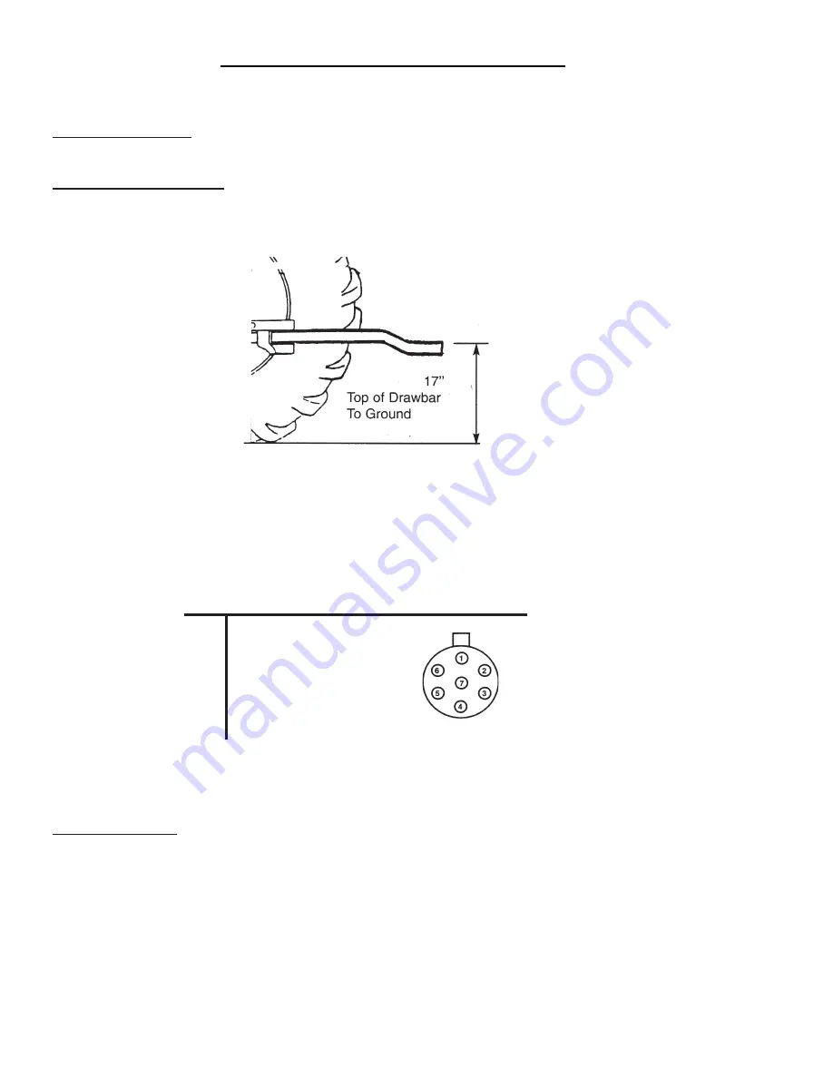
1. Set the drawbar should be set up at least 17 inches off the ground. The drawbar may need to be
“flipped”. This gives more clearance between the pole and left head for opening and closing.
2. Extend the drawbar to the farthest position to allow for easier turning. The three point arms should be
taken off the tractor to keep them from hitting the hydraulic shut-off valve located at the front of the pole.
3. The tractor must be equipped with a 1000 RPM 1-3/8” 21 spline PTO shaft.
4. The tractor needs to have a seven pin electric plug.
PREPARING FOR OPERATION
HYDRAULICS
The tractor hydraulic system should have a minimum flow of 5 GPM and a minimum pressure of 2000
PSI. This system is used to operate the pole cylinders and the cylinders controlling the pickup heads.
The PTO driven self-contained hydraulic system on the Merger provides oil to the hydraulic motors
operating the pickup belts and cross conveyor belts. The Merger pole is the hydraulic reservoir. In case
of a blown suction hose, shut off the tractor PTO, and turn off the valve located at the front of the pole.
The fans for the oil cooler radiators located on the merger pole must be turning properly to keep the oil
cool during merger operation. The oil filter should be replaced once a year and the oil should be replaced
every other year or when the oil becomes discolored.
Before first operation, check the entire Merger over carefully . Tighten bolts, set screws,
and chains that might have come loose in handling. Lubricate as explained in the
Lubrication Guide.
Содержание TWM12
Страница 4: ......
Страница 6: ...Intentionally Left Blank 4...
Страница 8: ...Intentionally Left Blank 6...
Страница 11: ...SAFETY DECALS 9...
Страница 13: ...11...
Страница 27: ...LUBRICATION GUIDE 10 9 2 1 1 1 2 9 10 1 25 5 6 6 6 7 7...
Страница 28: ...LUBRICATION GUIDE 1 10 9 9 5 2 10 2 26 3 3 7 7 HYDRAULIC BRAKE OPTION 3...
Страница 31: ...DECAL LOCATION 29 1494L 12803 B 82602 11599 72203A 311 12803 A 54034 11599 8474 8475 3398A 7608B DCAMB 31401...
Страница 35: ...33 SERVICE NOTES...
Страница 36: ...34 SERVICE NOTES...
Страница 37: ......


