


GB
57
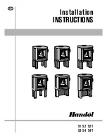
Supply of
combustion air
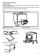
Combustion air can be provided directly via a duct
from outside, or indirectly via a vent in the outer
wall of the room where the stove is to be placed.
The amount of combustion air used for combustion
is approximately 25 m
3
/h.
Some installation alternatives are shown to the
right. On certain models, H54 and H54T, when
supply air is retrieved via walls behind, there is a
knock out for inserting the combustion air hose,
see figure below.
The air duct connection on the stove has an
external diameter of Ø64 mm.
In hot areas the duct should be insulated with 30
mm mineral wool covered with a moisture inhibitor
(plastic). It is important that the lead-in between
the pipe and the wall (or floor) is sealed using
jointing compound. When duct routing for further
than 1 m the pipe diameter must be increased to
100 mm and a correspondingly larger wall vent
must be selected.
A 1 m length of condensation insulated ducting for
combustion air is available as an accessory.
HK
HK
HK
HK
30 mm
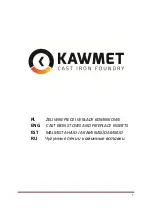
Cover for
H51, H52, H52T and 53
Ducting to cover the outdoor air connection hose
is available (accessory). The duct can be installed
after the stove is installed.
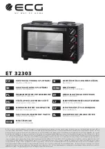
Knock out on H54 and H54T
To insert the combustion air hose, the knockout in
the base is tapped out using a hammer, remember
to protect the floor.