English
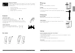
Battery information on the display
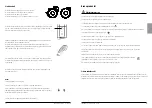
The battery discharging will be shown in four stages:
Battery state 1
: The battery is ok, no need for charging (100 - 50 %).
Battery state 2
: Battery needs charging. (50 - 25 %)
Battery state 3:
Battery needs charging. (Less than 25 %) A tone sounds when a button is pressed in
this battery state.
Battery state 4
: The battery needs charging. (17V or lower) At this stage some of the functionality of the
lift is lost.At this battery stage it is only possible to drive the lift arm down. Furthermore an audio signal
will sound when a control button is activated. The symbol will switch between the two pictures for 10
seconds.
The battery symbol is shown when the control box is active until power down (2 minutes after use).
It is not possible to use other batttery types than BAJ1/BAJ2.
The battery level is measured via voltage. This means that it is possible to experience e.g. that the
battery switches from state 1 to state 2 and back to state 1.
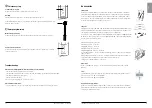
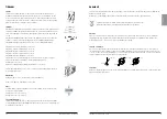
Charging batteries
A tone sounding when using the lift indicates that the battery need recharging.
Charge the lift after use to ensure that the battery is always fully charged.
Lock the castor wheels when charging the battery.
1. Connect the charging cable to a power outlet and in the connection for charger cable.
The symbol for charging is shown on the display.
2. Check to ensure that the lamps on the control box light up. The green LED lamp indicates that the
charger is receiving power and the yellow LED lamp indicates that the battery is charging.
3. Charging stops automatically when the battery is fully charged.
Wall-mounted charger
1. Remove the battery pack from the lift and place it in the wall-mounted charger.
2. Check to ensure that the LED lamp on the front of the charger lights up.
NOTE!
Before the lift is used for the first time, it must be charged for at least 4 hours.
For maximum battery life, charge batteries regularly. We recommend daily charging when the lift is
used daily.
The emergency stop must be deactivated during charging.
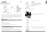
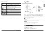
Eva450EEL
Eva600EEL
Eva450EML
REVISION HISTORY
REV.
DESCRIPTION
DATE
APPROVED
D
E
F
C
1
2
3
4
B
A
3
2
1
5
C
D
4
6
7
8
A
B
SCALE:1:10
DWG. NO.
REV.
NAME
DATE
DRAWN
APPROVED BY
SHEET 1 OF 1
WEIGHT:
COMMENTS:
STATUS:
TITLE
MATERIAL:
SIZE
Released
EVA EEL 450 base
90001288
02
g
2011-05-20
A3
Unless otherwise stated, general
tolerances according to ISO 2768-m
hc-jope
This drawing and any information or descriptive matter set out hereon are the confidential and copyright property of Handicare
and must not be disclosed, loaned, copied or used for manufacturing, tendering or any other purpose without their written permission.
EE
EE
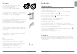
Service information read-out
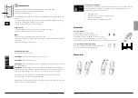
Basic service information can be read out on the display. To get the service information on the
display please press the lift arm up button for half a second. The information will be shown for
½ minute or until other buttons are activated.
•
Total cycles done by the actuator
•
Total work done by the actuator (ampere usage times seconds in use)
•
Total number of overloads
•
Days since last service/Days between services
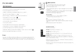
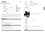
Hand control
Raising/lowering the lift arm
Symbol indicate direction of travel.
Motion stops as soon as the button is released.
If the lift arm encounter an obstacle while lowering, the lift will
immediately stop the motion. In order to continue, the lift arm will
need to be raised slightly by using the hand control before further lowering.
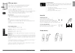
Electrical base-width adjustment (EE)
Markings on the buttons of the hand control indicate function.
Motion stops as soon as the buttons are released.
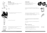
Changing the battery
”Click!”
1
2
8
9
I N S T R U C T I O N S F O R U S E
I N S T R U C T I O N S F O R U S E


