HAMWORTHY HEATING LTD
26
FLEET W series
500001211/F
8 CONTROLS OPERATION
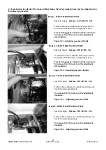
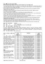
5. Energise electrical supply and start the boiler module. The burner will ignite and run at 100% modulation.
6. Monitor the combustion readings on the combustion analyser at both Maximum and Minimum firing rates - refer
to section 8.2.8.2 - Controller Stop function.
*
Figure must not exceed 100ppm under normal operating conditions.
If combustion readings fall within the required range the boiler module is set and operating correctly. If the
combustion readings fall outside the required range the burner settings will require adjustment.
CONTACT HAMWORTHY HEATING TECHNICAL DEPARTMENT FOR FURTHER DETAILS
7. Shut down the boiler and isolate from the electrical supply. Remove instrumentation and replace test points and plugs.
8. Refer to
section 8.1 - Controls Operation,
to adjust the relevant boiler settings specific to the installation
7.7 Setting the flow rate to achieve 20°C
∆
T
Before commissioning is complete, the flow rate must be checked and adjusted. A ball valve is located on the boiler return
pipe, prior to the pump, and controls the flow through the boiler. Using the boiler flow and return temperature sensors
visible on the display via the LMU programme. This
MUST
be carried out with the boiler running at
maximum
firing rate.
The 20°C
∆
T condition across the boiler must be set as follows;
1
Run boiler at maximum rate.
2
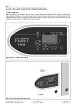
Monitor flow temperature (displayed on main screen of HMI).
3
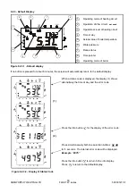
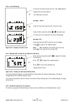
As boiler flow temperature rises, between 60°C & 80°C , press info button (to enter information mode) then
hold down up/down arrows for 3 seconds (to enter extended information mode) use + button to scroll to b1
which displays boiler return temperature.
4
Within the case, locate the ball valve on the return pipe of the boiler, and then adjust to give 20°C
differential between flow and return temperature. Opening the valve will decrease the differential/closing the
valve will increase the differential.
Press mode button to exit back to main screen and check flow temperature. It may be necessary to repeat the
sequence several times to ensure an accurate 20°C delta T is set.
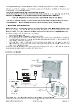
Figure 8.2 - System configuration of boiler control (LMU) & system peripherals
LMU
QAC34 ..
Roo m Thermostat
/ T ime Switch
RVA47
Bu ilding Automation /
Remote Management
Service Tool
OCI420
AGU2.50 0
AGU2.51xx
LPB
Clip-in
Auxiliary mod ules
0..10 V
4..20 mA
OCI /ACS
E
B
A
RVS controller
Содержание F100W
Страница 2: ......
Страница 37: ...HAMWORTHY HEATING LTD 31 FLEET W series 500001211 F Figure 8 2 1 3 Operation and display philosophy...
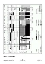
Страница 46: ...HAMWORTHY HEATING LTD 40 FLEET W series 500001211 F Figure 8 3 11 Operating phases...
Страница 79: ...Please complete the information on the Registration card cut out and return to Hamworthy Heating Ltd...
Страница 80: ......
Страница 81: ......


