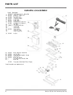
HAMPTON BAY Hampton H25-NG Скачать руководство пользователя страница 32

32

Hampton H25 Direct Vent Freestanding Gas Stove

AUTOMATIC

CONVECTION FAN

OPERATION

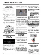
The fan operates automatically - turn the knob
at the top right rear corner to adjust to the
desired speed. The fan will turn on as the stove
comes up to operating temperature. After the
unit has been turned off and the unit cooled to
below a useful heat output range the fan will
shut off automatically.

ADJUSTING FLAME

HEIGHT

Your heater has an adjustable flame to tailor the
look and heat output to your specific needs. It
is adjusted by turning the flame adjustment dial
on the gas control valve.

Turn clockwise to adjust the flame higher,
counterclockwise for a lower flame.

OPERATING INSTRUCTIONS

OPERATING

INSTRUCTIONS

1)

Read and understand these instructions
before operating this appliance.

2)

Check to see that all wiring is correct and
enclosed to prevent possible shock.

3)

Check to ensure there are no gas leaks.

4)

Make sure the glass in the door frame is
properly positioned. Never operate the
appliance with the glass removed. Never
strike the glass.

5)

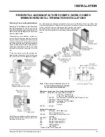
Verify that the venting and cap are unob-
structed.

6)

Verify log placement. If the pilot cannot be
seen when lighting the unit - the logs have
been incorrectly positioned.

7)

The unit should never be turned off, and on
again without a minimum of a 60 second
wait.

detectors in the house may go off at this time.
Open a few windows to ventilate the room for
a couple of hours. The glass may require
cleaning.

DO NOT ATTEMPT TO CLEAN THE GLASS
WHILE IT IS STILL 

HOT

!

Note: When the glass is cold and the

appliance is lit, it may cause con-
densation and fog the glass. This
condensation is normal and will
disappear in a few minutes as the
glass heats up.

DO NOT BURN THE APPLIANCE
WITHOUT THE GLASS FRONT IN
PLACE.

During the first few fires, a white film
may develop on the glass front as part
of the curing process. The glass should
be cleaned or the film will bake on and
become very difficult to remove. Use a
non-abrasive cleaner and NEVER clean
the glass while it is hot.

1)

Turn stove OFF using the Burner "ON/OFF"
switch  remote or thermostat. Switches are
located at the top right hand corner (rear)
of the stove.

2)

Turn gas control knob so indicator points to
"OFF" position and allow 5 minutes for any
gas in the combustion chamber to escape.

3)

Turn gas control knob counterclockwise so
indicator points to the "PILOT" position.
Depress the gas control knob fully. De-
press the igniter button several times until
the pilot lights. After approximately one
minute, release the gas control knob. The
pilot flame should continue to burn. If the
pilot does not remain lit, repeat operation
allowing a longer period before releasing
gas control knob.

4)

When the pilot stays lit, turn the gas knob
further counterclockwise to the "ON" posi-
tion.

5)

Use the thermostat or remote control to turn
on the unit.

6)

Rotate the flame height regulator to adjust
the flame height higher or lower.

SHUTDOWN

PROCEDURE

1)

Use the thermostat or remote control to turn
off the main burner.

2)

Turn the main gas control clockwise to the
"OFF" position to turn off the pilot (push
knob in slightly).

3)

Turn off all electric power to appliance if
service is to be performed.

FIRST FIRE

The 

FIRST FIRE

 in your stove is part of the paint

curing process. To ensure that the paint is
properly cured, it is recommended that you burn
your fireplace for at least four (4) hours the first
time you use it with the fan on. When first
operated, the unit will release an odour caused
by the curing of the paint and the burning off of
any oils remaining from manufacturing. Smoke

LIGHTING

PROCEDURE

IMPORTANT: Gas cock knob cannot be
turned from "PILOT" to "OFF" unless it is
partially depressed.

IMPORTANT

To ignite or reignite the pilot,

the door to the firebox must

be opened.

Only when the pilot holds, without pressure
being applied to the control knob, should the
door to the firebox be closed. The unit 

must

never

 be operated with the glass or door

open.

Содержание Hampton H25-NG

Страница 1: ...What to do if you smell gas Do not try to light any appliance Do not touch any electrical switch do not use any phone in your building Immediately call your gas supplier from a neighbour s phone Foll...

Страница 2: ...and crafted appliance and has been designed to provide you with all the warmth and charm of a wood fireplace at the flick of a switch The model H25 has been approved by Warnock Hersey for both safety...

Страница 3: ...formation 6 Installation Checklist 6 Clearances to Combustibles 6 Locating Your Gas Stove 7 Manufactured Mobile Home Requirements 7 Combustion and Ventilation Air 7 Optional Fan Installation 7 Venting...

Страница 4: ...ton units are constantly being improved Checkthelabelontheunitandifthere isadifference thelabelontheunitisthecorrect one For the State of Massachusetts installation and repair must be done by a plumbe...

Страница 5: ...ured USA only or mobile home where not prohibited by local codes This appliance is only for use with the type of gas indicated on the rating plate This appliance is not converti ble for use with other...

Страница 6: ...onal Fan see page 7 3 Set vent restrictor page 9 4 Install venting Check all venting require ments pages 9 13 Vertical Termination with Co linear Flex System page 16 Hor izontal Termination Kits page...

Страница 7: ...N OPTIONAL FAN INSTALLATION Fan Kit Contains Qty Description 1 Fan Assembly c w green wire attached 1 Thermodisc 1 power cord 2 2 1 4 x 20 hex nut 1 Fan Speed Control 2 Remove the rear access panel on...

Страница 8: ...tove and secure with the 2 supplied bolts 2 1 4 20 hex head 12 Before re attaching the rear access panel the valve wires and the fan wires need to be connected Re connect the red and grey valve wires...

Страница 9: ...y Warnock Hersey These units use the balanced flue technol ogy Co Axial system The inner liner vents productsofcombustiontotheoutsidewhilethe outer pipe draws outside combustion air into the combustio...

Страница 10: ...p min 12 30cm with Riser Vent min 6 15cm H Not to be installed above a meter regulator assembly within 3 90cm horizontally from the centerline of the regulator J Clearance to service regulator vent ou...

Страница 11: ...h 7 Black N A N A 4D7AB Adjustable Length 12 Galvinized N A N A 4D12A Adjustable Length 12 Black N A N A 4D12AB 45O Elbow Galvinized 945 4DT EL45 4D45L 45O Elbow Black 945B 4DT EL45B 4D45LB 45O Elbow...

Страница 12: ...onal Ltd Dura Vent and Direct Vent GS are registered and or proprietary trademarks of Simpson Dura Vent Co Inc ThisproducthasbeenevaluatedbyIntertekfor using a Dura Vent Flue Adaptor in conjunction wi...

Страница 13: ...he vent is ENCLOSED in a chase min size 9 x 9 maintain a 1 1 4 clearance to combustibles May be installed in Manufactured Mobile Homes after first sale Horizontal Terminations for All Venting Systems...

Страница 14: ...ipe length is 30 feet with min of 8 feet total vertical and max 8 feet total horizontal Please note min 1 foot between 90o elbows is required With these options maxi mum total pipe length is 30 feet w...

Страница 15: ...e note min 1 foot between 90o elbows is re quired Option H H1 V A 2 Max 2 Min B 3 Max 3 Min C 4 Max 4 Min D 5 Max 5 Min E 6 Max 6 Min Withtheseoptions max total pipelengthis30feetwithmin of 6 feet tot...

Страница 16: ...ting Arrangements chart below for minimum and maximum flue lengths See chart below for minimumdistancesfromroof Periodicallycheck that the vent is unrestricted Masonry chimneys may take various contou...

Страница 17: ...e to length Attach the 45o elbow to the rigid pipe and ensure that the pipe length when cut with the 45o elbow will seat onto both the starter collar and the 90o elbow Crimped sec tionofrigidpipeseats...

Страница 18: ...fit of the liner onto the 4 dia starter collar 8 Cut the 4 dia flex liner to the desired size Hint leaveanextra12 to16 oflength this willmakethefinalassemblyeasiertowork with 9 Securethe4 dia flexline...

Страница 19: ...to the wall It is also important to notethewallthickness Beforecuttingthevent hole through the wall ensure that ALL vent and termination clearances see page 10 will be met If this is an outside corner...

Страница 20: ...pipe and nearby combustible surfaces is 1 1 4 inch Be sure to check the vent termination clearance require ments from decks windows soffits gas reg ulators air supply inlets and public walkways as sp...

Страница 21: ...equired Other parts may be re quired for your particular installa tion See above for a list of vent parts Ifinstallingterminationonasidingcoveredwall a vinyl siding standoff or furring strips can be u...

Страница 22: ...he Backing Plate into the wall pene tration heat shield and attach using 4 screws Dia 4 8 Connect all pipe sections to unit and install into wall a Measure pipe length required and cut to length Hint...

Страница 23: ...re sili cone to the out er pipe before connecting the inner pipe 4 Assemblethedesiredlengthsofblackpipe and elbows necessary to reach from the appliance adapter up though the Round Support Box Insure...

Страница 24: ...n place and sealed before installing a Direct Vent sys tem within the chimney If the appliance shuts off during opera tion contact a qualified service person to determine if a negative pressure and or...

Страница 25: ...rities and the CAN CGA B149 installation codes ForUSAinstallationsfollowlocalcodesand or the current National Fuel Gas Code ANSI Z223 1 When using copper or flex connectors use onlyapprovedfittings Al...

Страница 26: ...authorized Hampton Installer at the time of installation or service 4 Light the pilot and turn the valve to ON position Read manometer 5 The pressure check should be carried out with the unit burning...

Страница 27: ...hold on to the elbow behind the orifice 9 Reinstall new burner orifice LP stamped 54 and tighten 10 Reverse steps 3 to 2 11 Attach the Conversion label This unit has been converted to Propane on top...

Страница 28: ...lly and refer to the dia grams If the logs are broken do not use the unit until they are replaced Broken logs can interfere with the pilot operation The gas log kit contains the following a Rear Log 9...

Страница 29: ...oto below 7 Place the center cross log on the locating pin in the top of the rear log and position as shown below Logs must be oriented as shown below 8 Test fire to ensure proper light off make sure...

Страница 30: ...n interior wall Hamptonoffersanoptionalprogrammablether mostat but any 250 750 millivolt rated non anticipator type thermostat that is CSA ULC or UL approved may be used 14 GA 16 GA 18 GA 20 GA 22 GA...

Страница 31: ...are away from sharp edges WARNING Electrical Grounding Instructions This appliance is equipped with a three pronged grounding plug for your protection against shock haz ard and should be plugged dire...

Страница 32: ...rocess Theglassshould be cleanedor the film will bake on and become very difficult to remove Use a non abrasive cleaner and NEVER clean the glass while it is hot 1 TurnstoveOFFusingtheBurner ON OFF sw...

Страница 33: ...Hampton H25 Direct Vent Freestanding Gas Stove 33 Copy of the Lighting Plate instructions OPERATING INSTRUCTIONS...

Страница 34: ...Body Firebox Different types and thicknesses of steel will expandandcontractatdifferentratesresulting in some cracking and ticking sounds will be heard throughout the cycling process WARNING CHILDREN...

Страница 35: ...ions orfittingshavebeendisturbed andconse quently loosened Also check mechanical supportssuchasWallStraps orplumbers tape for rigidity 5 Verify proper operation after servicing LOG REPLACEMENT Theunit...

Страница 36: ...alve assembly continue 14 Remove two 2 thermopile wires 15 Removethermocouplewitha9mm metric wrench 16 Remove pilot nut with an 11 mm wrench 17 Remove valve to orifice nut with a 13 16 wrench 18 Remov...

Страница 37: ...tion Part Description Part Description 50 W260260 Top Relief Frame Gasket 51 942 117 Top Relief Frame 52 W260280 Top Relief Plate Gasket 53 290 021 Top Relief Plate 54 Capscrew 1 4 x 1 3 4 NC 55 Side...

Страница 38: ...Pilot Assy S I T 3 flame LP 67 Pilot Holder 68 W840470 Pilot Assembly Gasket 69 Valve Shield 70 Valve Bracket 71 260 042 Valve Gasket 73 Valve Cover Plate 74 Valve Access Door 75 350 930 Log Set Part...

Страница 39: ...turned to FPI and evaluated for manufacturer defect The authorized selling dealer is responsible for all in field service work carried out on your Waterford product FPI will not be liable for results...

Страница 40: ...________________________________________________ Printed in Canada Hampton is a trademark of FPI Fireplace Products International Ltd Hampton fireplace products are designed with reliability and simpl...

Отзывы: