


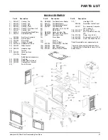
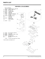

Hampton H25 Direct Vent Freestanding Gas Stove
23
INSTALLATION
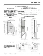
Offset Chart
Diagram 12
7)
Ensure vent is vertical and secure the base
of the flashing to the roof with roofing rails,
slide storm collar over the pipe section and
seal with a mastic.
8)
Install the vertical termination cap by twist
locking it.
Notes:
a)
For multistorey vertical installations, a
Ceiling Fire stop (Part # 963) is required
at the second floor, and any subse-
quent floor. Diagram 12. The opening
should be framed to 10 " x 10" inside
dimensions, in the same manner as
shown in diagram 9.
b)
Any occupied areas above the first
floor, including closets and storage
spaces, through which the vertical
vent passes, must be enclosed.
Diagram 11
Roof Pitch Minimum Vent Height
Feet Meters
flat to 7/12
2
0.61
over 7/12 to 8/12
2
0.61
over 8/12 to 9/12
2
0.61
over 9/12 to 10/12
2.5
0.76
over 10/12 to 11/12
3.25
0.99
over 11/12 to 12/12
4
1.22
over 12/12 to 14/12
5
1.52
over 14/12 to 16/12
6
1.83
over 16/12 to 18/12
7
2.13
over 18/12 to 20/12
7.5
2.29
over 20/12 to 21/12
8
2.44
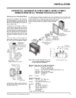
Diagram 9
the venting system. You may wish to relo-
cate the appliance or to offset, as shown in
diagram 8 to avoid cutting load bearing
members.
Diagram 8
3)
To install the Round Support Box/Wall Thim-
ble in a flat ceiling, cut a 10 inch square hole
in the ceiling centred on the hole drilled in
Step 2. Frame the hole as shown in diagram
9.
Hint: Apply the
sealant (Mill-Pac
and/or high tem-
perature sili-
cone) to the out-
er pipe before
connecting the
inner pipe.
4)
Assemble the desired lengths of black pipe
and elbows necessary to reach from the
appliance adapter up though the Round
Support Box. Insure that all pipes and
elbow connections are in the fully twist-
locked position and sealed.
Diagram 10: The upper half of the flashing is
installed under the roofing material and not
nailed down until the chimney is installed.
This allows for small adjustments.
Note: If an offset is necessary in the
attic to avoid obstructions, it is
important to support the vent pipe
every 3 feet, to avoid excessive
stress on the elbows, and possi-
ble separation. Wall straps are
available for this purpose. See
diagram 5.
Galvanized pipe and elbows may be uti-
lized in the attic as well as above the
roofline. The galvanized finish is desirable
above the roofline due to its higher corro-
sion resistance.
Continue to add pipe sections through the
flashing until the height of the vent cap
meets the minimum height requirements
specified in diagram 11 or local codes.
Note that for steep roof pitches, the ver-
tical height must be increased. A poor
draft, or down drafting can result from
high wind conditions near big trees or
adjoining roof lines, in these cases, in-
creasing the vent height may solve the
problem.
5)
Cut a hole in the roof centred on the small
drilled hole placed in the roof in Step 2. The
hole should be of sufficient size to meet the
minimum requirements for clearance to
combustibles of 1-1/4". Slip the flashing
under the shingles (shingles should over-
lap half the flashing) as per diagram 10.
6)
Continue to assemble pipe lengths.


