


22
Subject to change without notice
Short Instruction for HM303-
6
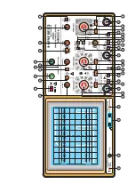
Switching on and initial setting
Connect instrument to power outlet, depress red
POWER
button. LED indicates operating condition.
Case, chassis and all measuring terminals are connected to the safety earth conductor (Safety Class I).
Do not depress any further button.
TRIG.
MODE
selector switch to
AC
.
AT/NM
button released,
CH I
input coupling switch to
GD
, set
TIME/DIV.
switch to 50µs/div.
Adjust
INTENS
control for average brightness.
Center trace on screen using
X-POS.
and
Y-POS.I
controls. Then focus trace using
FOCUS
control.
Vertical amplifier mode
Channel I:
CH I/II
,
DUAL
and
ADD
pushbuttons in out position.
Channel II:
CH I/II
pushbutton depressed.
Channel I and II:
DUAL
pushbutton depressed. Alternate channel switching: ADD (
CHOP.
) pushbutton in out position.
Signals <1kHz or time coefficient ³1ms/div:
DUAL
and ADD (
CHOP.
) buttons depressed.
Channel I+II (sum): depress only
ADD
button.
Channel I-II (difference): depress
ADD
and
INV.
pushbuttons.
Triggering mode
Select trigger mode with
AT/NM
pushbutton:
AT
= Automatic Peak (value) Triggering <20Hz to 60MHz (out position).
NM
= Normal Triggering (depressed).
Trigger edge direction: select slope with
SLOPE (
)
pushbutton.
Internal triggering: select channel with
TRIG. I/II (CH I/II)
pushbutton.
Alternating triggering (internal):
DUAL
and
ALT.
pushbuttons depressed, ADD (
CHOP
.) pushbutton in the out position.
External triggering:
TRIG. EXT.
pushbutton depressed; sync signal (0.3V
pp
to 3V
pp
) to
TRIG. EXT.
socket.
Line triggering (normal triggering):
AT/NM
and
ALT
pushbuttons depressed (
~
).
Select trigger coupling with
TRIG. MODE
selector switch. Trigger frequency ranges:
AC
: >20Hz to 100MHz;
DC
: DC to 100MHz;
LF
: DC to 1.5kHz.
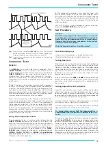
TV
: Composite video signal with line or horizontal frequency.
TIME/DIV. 0.2s/div. - 1ms/div.
= field frequency
TIME/DIV. 0.5ms/div. - 0.1µs/div.
= line frequency
Select edge direction with
SLOPE (
)
pushbutton (sync. pulse above
/
, below
\
).
Pay attention to trigger indicator:
TR
LED above the
SLOPE
pushbutton.
Measurements
Apply test signal to the vertical input connectors of
CH I
and/or
CH II
.
Before use, calibrate attenuator probe with square wave
CALIBRATOR
-signal.
Switch input coupling to
AC
or
DC
.
Adjust signal to desired display height with attenuator switch (
VOLTS/DIV.
).
Select time coefficient on the
TIME/DIV.
switch.
Set trigger point with
LEVEL
knob for normal triggering.
Trigger complex or aperiodic signals with longer
HOLD OFF
-time.
Amplitude measurement with Y fine control at right stop (
CAL.
).
Time measurement with time fine control at right stop (
CAL.
).
Horizontal expansion 10 fold with
X-MAG. x10
button depressed.
External horizontal deflection (
X-Y mode
) with
XY
pushbutton depressed (X input:
CH I
).
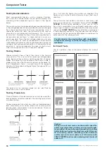
Component Tester
Press
COMP. TESTER
pushbutton (on). Connect both component terminals to
COMP. TESTER
jacks.
In-circuit test:
Circuit under test must be disconnected from battery or power (pull out power plug), signals and ground (earth).
Remove all signal connections to HM303-6 (cable, probe), release X-MAG. X10 pushbutton, then start testing.
Содержание HM303-6
Страница 1: ...O s c i l l o s c o p e H M 3 0 3 6 Manual English...
Страница 23: ...M A N U A L H A N D B U C H M A N U E L...


