Hameg HM303-6 Скачать руководство пользователя страница 21

21

Subject to change without notice

Element

Function

DUAL

Button released:
one channel only.

(pushbutton

Button depressed: channel I

switch)

and channel II in alternating
mode.

CHOP.

DUAL and ADD buttons depressed:
CH I and CH II in chopped mode.

ADD

ADD depressed only:

(pushbutton switch)

algebr. addition.
In combination with INV.:
difference.

VOLTS/DIV.

Channel II input attenuator.

(12 position

Selects Y input sensitivity

rotary switch)

in mV/div. or V/div.
in 1-2-5 sequence.

VAR. GAIN

Fine adjustment of Y amplitude

(knob)

CH II. Increases attenuation
factor min. by 2.5 (left hand stop).
For amplitude measurement
must be in CAL. position (right
hand stop).

TRIG. MODE

Trigger selector:

(switch)

AC

: 10Hz-100MHz.

AC-DC-LF-TV

DC

: DC-100MHz.

LF

: DC-1.5kHz.

TV:

 Triggering for frame and line.

AT/NM

Button released = autom. trig.

(pushbutton

trace visible without input signal.

 switch)

Button depressed = normal trig.
with  LEVEL


adjustment.


~

AT/NM

 and 

ALT

 pushbuttons

depressed:
Internal line triggering in combi-
nation with normal triggering.

ALT

Triggering alternates between

(pushbutton switch)

CH I and CH II in alternating
DUAL Channel mode only.

HOLD OFF

Controls holdoff-time

(knob)

between sweeps.
Normal position = full ccw.

TIME/DIV

.

Selects time coefficients

(rotary switch)

(speeds) of time base,
from 0.2s/div. to 0.1µs/div.

Variable

Variable adjustment of time base.

time base control

Decreases time deflection speed

(center knob)

at least 2.5 fold.
For time measurements
turn to right hand stop.

Element

Function

XY

Selects X-Y operation,

(pushbutton switch)

stops sweep.
X signal via CH I.
Attention!
Phosphor burn-in without signal.

TRIG. EXT.

Button released = internal trig.

(pushbutton switch)

Button depressed = external
triggering, trigger signal via TRIG.
EXT. BNC socket.

INPUT CH I

Channel I signal input and input

(BNC socket)

for horizontal deflection in X-Y
mode.
Input impedance 1M

Ω 

II 20pF.

AC-DC

Selects input coupling of CH I

(pushbutton switch)

vertical amplifier.
DC = direct coupling
AC = coupling via capacitor.

GD

GD = signal disconnected

(pushbutton  switch)

from input, Y amplifier grounded.

Connector for reference potential

(4mm  socket)

(galvanically connected to earth).

INPUT CH II

CH II signal input.

(BNC socket)

Input impedance 1M

Ω 

II 20pF.

AC-DC

Selects input coupling of the CH II

(pushbutton  switch)

vertical amplifier. Specs see (29).

GD

GD = signal disconnected

(pushbutton  switch)

from input, Y amplifier grounded.

INV.

Inversion of CH II display.

(pushbutton switch)

In combination with ADD button
= difference CH I, CH II.

TRIG. EXT.

Input for external trigger signal.

(BNC socket)

(Pushbutton TRIG. EXT. depressed.)
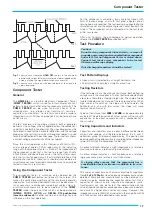
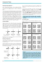
COMP. TESTER

Switch to convert oscilloscope

(pushbutton switch)

to component tester mode.
Release X-MAG. X10 pushbutton.

COMP. TESTER

Connectors for test leads

(4mm sockets)

of the Component tester.

0.2Vpp

Calibrator square wave output

(test socket)

0,2V

pp

.

CALIBRATOR
1kHz/1MHz

Selects calibrator frequency.

(pushbutton switch)

Button released: approx. 1kHz,

Button depressed: approx. 1MHz.

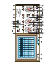
Front Panel Elements HM 303-

6

  (Brief Description  -  Front View)

Содержание HM303-6

Страница 1: ...O s c i l l o s c o p e H M 3 0 3 6 Manual English...

Страница 2: ...lifiers 12 X Y Operation 13 Phase comparison with Lissajous figures 13 Phase difference measurement 13 in DUAL mode 13 Phase difference measurement in DUAL mode 14 Measurement of an amplitude modulati...

Страница 3: ...effected by such fields Although the interior of the oscilloscope is screened by the cabinet direct radiation can occur via the CRT gap As the bandwidth of each amplifier stage is higher than the tot...

Страница 4: ...oise Amplifiers Time Base 0 2 s 100 ns cm with X Magnification to 10 ns cm Triggering from 0 to 50 MHz from 5 mm signal level 100 MHz 8 mm Analog mode provides unexcelled signal presentation at high r...

Страница 5: ...1 s div 1 2 5 Sequence Accuracy 3 Variabel uncalibrated 2 5 1 to 0 5 s div X Magnification x 10 up to 10 ns div Accuracy 5 Hold Off Time variable to approx 10 1 XY Bandwidth X Amplifier 0 2 5 MHz 3 d...

Страница 6: ...Without pulling the locking knobs they will latch in into the next locking position Handle mounting dismounting The handle can be removed by pulling it out further depending on the instrument model in...

Страница 7: ...e atmosphere or if there is danger of explosion The operating position may be any however sufficient ventilation mustbeensured convectioncooling Prolongedoperationrequires the horizontal or inclined p...

Страница 8: ...83 times the potential difference in Vpp The relationship between the different voltage magnitudes can be seen from the following figure Voltage values of a sine curve Vrms effective value Vp simple p...

Страница 9: ...frequency Depending on the time base setting of the TIME DIV switch one or several signal periods or only a part of a period can be displayed The time coefficients are stated in s div ms div and s div...

Страница 10: ...d The attenuator switch must then be turned back to the left until the vertical signal height is only 3 8div With a signal amplitude greater than 160Vpp an attenuator probe must be inserted before the...

Страница 11: ...be visible after a short warm up period of approx 10 seconds Adjust Y POS I and X POS controls to center the baseline Adjust INTENS intensity and FOCUS controls for medium brightness and optimum sharp...

Страница 12: ...is slightly more difficult but causes a better result The rising edge should be as steep as possible with a pulse top remaining as straight and horizontal as possible After completion of the HF adjus...

Страница 13: ...uite simple with the following formula and a pocket calculator with trigonometric functions Apart from the reading accuracy the signal height has no influence on the result The following must be noted...

Страница 14: ...tion F 1 MHz f 1 kHz m 50 UT 28 3 mVrms If the two values a and b are read from the screen the modulation factor is calculated from where a UT 1 m and b UT 1 m The variable controls for amplitude and...

Страница 15: ...a positive potential That has nothing to do with zero or ground potential and absolute voltage values The positive slope may also lie in a negative part of a signal A falling edge sign triggers when...

Страница 16: ...ossible in this trigger mode External triggering The internal triggering is disconnected by depressing the TRIG EXT button The time base can be triggered externally via the TRIG EXT socket using a 0 3...

Страница 17: ...are required The test leads are connected to the insulated socket and the adjacent ground socket beneath the screen The component can be connected to the test leads either way round After use to retu...

Страница 18: ...can be identified by comparison with a known diode Testing Transistors Three different tests can be made to transistors base emitter base collector and emitter collector The resulting test patterns ar...

Страница 19: ...soldered This terminal should then be connected to the insulated COMP TESTER socket avoiding hum distortion of the test pattern Another way is a test pattern comparison to an identical circuit which i...

Страница 20: ...II display SLOPE Selects the slope of the trigger signal Element Function SLOPE rising edge pushbutton switch falling edge TR LED lights if sweep is triggered LED LEVEL Adjustment of trigger level kno...

Страница 21: ...ast 2 5 fold For time measurements turn to right hand stop Element Function XY Selects X Y operation pushbutton switch stops sweep X signal via CH I Attention Phosphor burn in without signal TRIG EXT...

Страница 22: ...ggering TRIG EXT pushbutton depressed sync signal 0 3Vpp to 3Vpp to TRIG EXT socket Line triggering normal triggering AT NM and ALT pushbuttons depressed Select trigger coupling with TRIG MODE selecto...

Страница 23: ...M A N U A L H A N D B U C H M A N U E L...

Страница 24: ...stra e 6 A Rohde Schwarz Company D 63533 Mainhausen registrierte Marke Tel 49 0 61 82 800 0 DQS Zerti kation DIN EN ISO 9001 2000 Fax 49 0 61 82 800 100 Reg Nr 071040 QM sales hameg de Oscilloscopes S...

Отзывы: