27
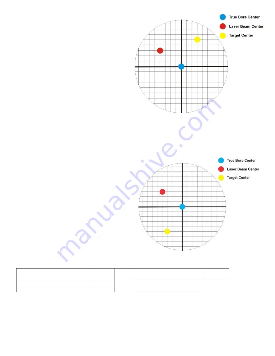
The readout always shows the displacement between the
Target Center and the Laser Beam Center. When the
Target Center is not on the True Bore Center, the
numbers and the signs on the readout will change when
the target is rotated because the Target Center is moved
to a different location in relationship to the laser beam.
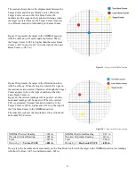
Figure 19 represents the target in the NORMal position,
with the cable
down
. If each square represents .001 in.,
the Target Center is .002 in. higher than the Laser Beam
Center (+.002 in.) and is .007 in. to the right of the Laser
Beam Center (+.007 in.).
Figure 19 – Target in the NORMal position
Figure 20 represents the target in the INverted position,
with the cable
up
. When the target is rotated, the
signs
on
the readout are also rotated. Therefore, although the Target
Center appears to be to the right of and lower than the
Laser Beam Center in
Figure 20, the vertical readings will be positive, and the
horizontal readings will be negative. When the vertical
TCE is calculated, (Normal Inverted divided by 2) the
Target Center is .004 in. higher and .003 in. to the right of
the True Bore Center in the NORMal position.
The table below shows the calculation of the vertical and
horizontal TSCE values.
Figure 20 – Target in the INverted position
NORMal Vertical Reading
+.002 in.
NORMal Horizontal Reading
+.007 in.
INverted Vertical Reading
+.008 in.
INverted Horizontal Reading
-.001 in.
Total
+.010 in.
Total
+.006 in.
Divide by 2 =
Vertical TSCE
+.005 in.
Divide by 2 =
Horizontal
TSCE
+.003 in.
If you place the Laser Beam Center exactly on the True Bore Center with the target in the NORMal position, the readings
will show Ve.005 in. and Hori.003 in.
Содержание L-702
Страница 1: ......
Страница 7: ...4 L 702 L 702SP Laser Dimensions...
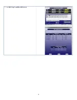
Страница 28: ...25 7 Lathe9 Step 3 and Results Screen...


