CJ
OM/20
09/re
v2/EN
14
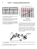
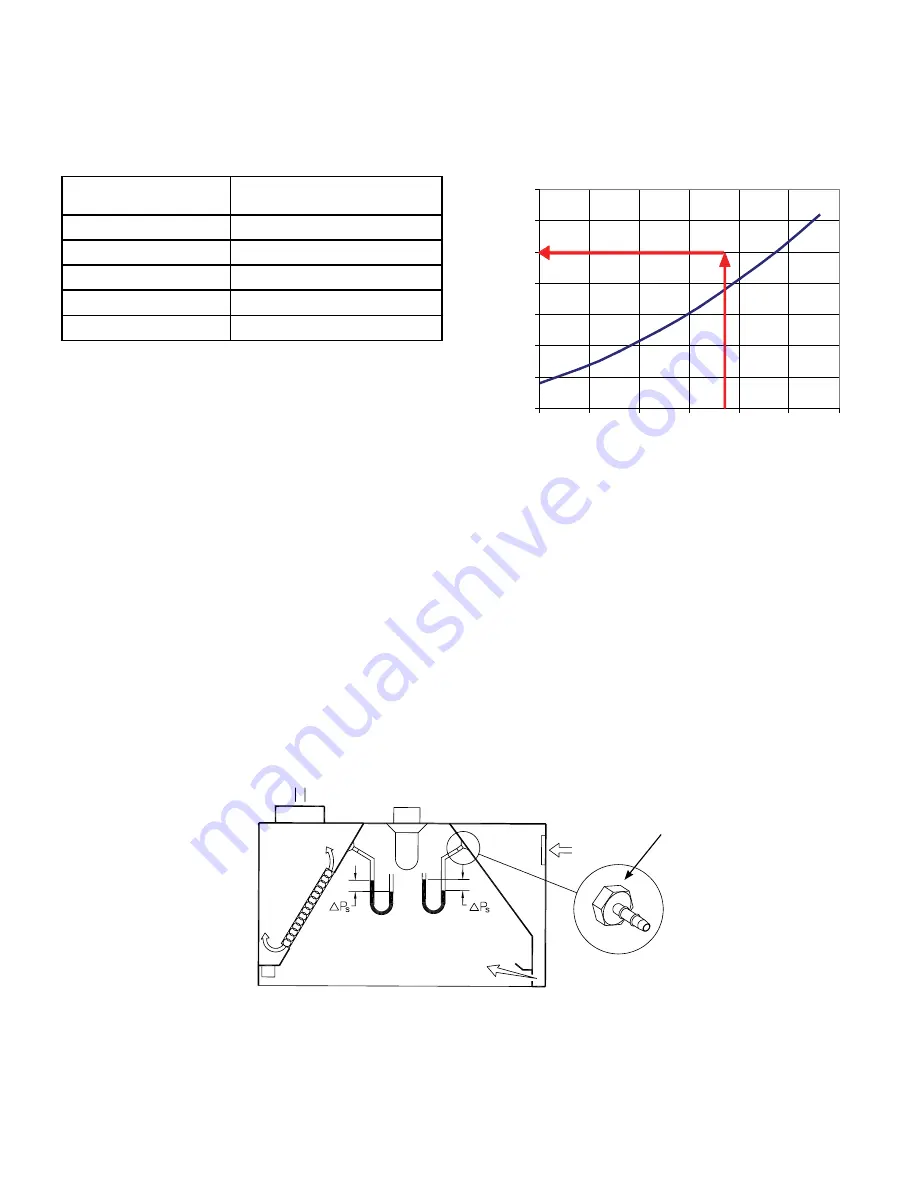
Exhaust T.A.B. Readings vs. Airflow
0.00
0.05
0.10
0.15
0.20
0.25
0.30
0.35
800
1050
1300
1550
1800
2050
2300
Airflow (cfm)
T.A.B. Reading (In. WC)
This example shows how to determine the correct T.A.B.
port reading for the exhaust hoods.
In this example, a design airflow of 1700 cfm is selected
from the Airflow axis, and a vertical line is drawn up to
the T.A.B. pressure curve for this hood.
A horizontal line is then drawn for the T.A.B. pressure
curve to the T.A.B. reading axis on the left-hand side of
the chart and the corresponding pressure is read off the
chart as 0.19 inches of Water Column.
Capture Jet
®
T.A.B. Port Readings
Hood Model
Design T.A.B.
(inches WC)
KVE/KVC
0.25
KVW
0.25
KVR
0.25
KVL
0.29
T.A.B.™ - Testing and Balancing Ports
The Capture Jet
®
and exhaust air flows are easily and
accurately determined by measuring the pressure
difference from the T.A.B. (Testing and Balancing)
ports mounted in each plenum. The corresponding
air flows can be read from the diagram provided.
To properly measure T.A.B. port readings use a
magnehelic gauge or digital manometer and for
exhaust plenum reading hookup hose from negative
connection on instrument to T.A.B. Port on exhaust
plenum. Leave positive connection on instrument
open to atmosphere.
**** It is very important the cooking equipment is in operation to create a thermal plume, prior to the air balancer, to be able
to use the T.A.B. ports.
****For accurate results, the balance contractor should receive a copy of the job specific hood plans with the design T.A.B.
readings from the hood supplier prior to balancing.
Closeup view
of T.A.B. Port
Measured Pressure


