Supplied By www.heating spares.co Tel. 0161 620 6677
11
INSTALLING THE APPLIANCE
4
4.2
PREPARING THE WALL
Before installing the appliance ensure that the chosen location is
suitable (Section 3.2) and that the requirements for flue position,
(Section 3.3), & minimum clearances, (Section 2.4) are satisfied.
These minimum clearances are essential to provide access for
servicing, and are included on the wall mounting template.
a)
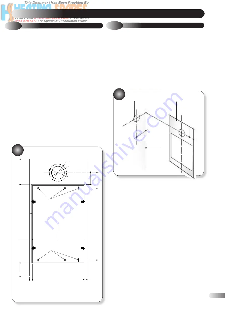
Take the template (Fig. 13) and tape the template onto the wall
in the desired position. (Ensuring that the centre line is level).
b)
Mark the position of the six wall mounting bracket fixing holes.
c) REAR OUTLET ONLY:
. If the installation is to use a rear
outlet, mark the position of the air/flue duct hole (from the
template) onto the rear wall.
4.1
UNPACKING THE APPLIANCE
The appliance and standard flue kit is supplied in a single cardboard
carton. In addition various optional flue kits are available as
described in section 2.5. If the appliance is to be installed without
access to the outside wall, a wall liner kit is also required.
Open the carton. Unpack the appliance, flue pack and any
option kits and check the contents against the following lists.
13
WALL MOUNTING TEMPLATE
14
MARKING THE POSITION OF A
SIDE FLUE
d) SIDE OUTLET ONLY:
If the installation is to use a LH or RH
side outlet, mark the position of the centre line of the air/flue
duct hole (from the template) onto the rear wall. Extend this
mark horizontally until reaching the side wall face, then draw
the position of the air/flue duct hole as detailed in Fig. 14.
e) VERTICAL OUTLET ONLY:
Using the wall template and the
dimensional information given in section 2.4 & 2.5. Calculate
where the boiler flue should be positioned and make the
necessary hole(s) in the ceiling/roof. Proceed to (k).
f)
ADDITIONAL ELBOW OR FLANGED DUCT WITH ELBOW:
Using the wall mounting template and the dimensional
information given in section 2.4 & 2.5. Calculate where the
boiler and flue are to be positioned and make the necessary
hole(s) in the wall(s)/ceiling/roof for the air/flue duct.
Proceed to (k).
g)
If the air/flue duct length is to be greater than 2.25m (88 in)
it is necessary to fit at least one support in the middle of the
duct. A support bracket kit is available as an optional extra.
Follow the fitting instructions provided with the bracket before
proceeding further.
h)
Remove the template and check the dimensions between the
centre lines of the flue and fixing holes shown in Fig. 13.
Drill the fixing holes using a 8mm masonry drill. Fit the
plastic plugs provided.
BOILER PACKAGE:
Boiler (Assembled.)
Installation, Servicing
and Users instructions.
Wall mounting template.
Plastic bags containing:
6 x Fixing screws.
Flue Turret Gasket.
2 x Split Pins.
6 x Rawl plugs.
2 x 28mm olives.
4 x screws for Flue turret.
Control knob.
FLUE COMPONENTS:
Inner wall sealing ring.
(white).
Telescopic flue assembly.
Outer wall sealing ring
(grey).
Flue turret elbow.
4 self tapping screws.
60mm dia. ‘O’ ring for
turret (fitted).
Dia ‘A’ Hole diameter 130mm if optional wall liner kit is to be used
for fitting flue/air duct from inside the room.
Dia ‘B’ Hole diameter 100mm if duct to be fitted from outside.
Dia ‘C’ Hole diameter to suit alternative wall liner (supplied by
installer) with an inside diameter between 127mm & 140mm.
OUTSIDE
OF CASING
OUTSIDE
OF WALL
BRACKET
TOP FIXING
HOLES
BOTTOM FIXING
HOLES
BOTTOM OF
APPLIANCE CASING
MINIMUM BOTTOM
CLEARANCE
12mm
12mm
DIA. "A"
DIA."B"
DIA."C"
200mm
95mm
180mm
550mm
100mm
MINIMUM LH SIDE
CLEARANCE 6mm
CENTRE LINE
BOILER FL
UE
MINIMUM RH SIDE
CLEARANCE 6mm
DUCT
CENTRE
LINE
WALL
TEMPLATE
POSITION OF
DUCT HOLE
CORNER OF
WALL
144mm


