


28
35
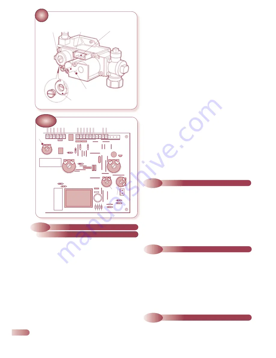
MULTIFUNCTIONAL GAS CONTROL
9.7
AIR PRESSURE SWITCH
9.8
OVERHEAT THERMOSTAT
9.9
PCB
a)
Remove the casing front panel and lower the control fascia
panel as described in section 9.6.1 step (a).
b)
Remove the PCB plastic cover (Fig. 32).
a)
Remove the casing front panel as described in section 9.1 step
(a) and remove the sealed chamber front panel (4 screws).
b)
Disconnect the pressure sensing pipes from the pressure switch
(note that the short pipe (from the flue gas sampling point) is
connected to the rear (-ve) connection on the pressure switch).
c)
Unscrew the two screws securing the pressure switch, and
transfer the electrical connections to the new switch.
d)
Fit the new pressure switch and re-assemble in reverse order
referring to the wiring diagrams (section 7) if necessary.
a)
Remove the casing front panel and lower the controls fascia
panel as described in section 9.6 step (a).
b)
Unclip the thermostat phial from the pipe, and disconnect the
two electrical connections (Fig. 36).
c)
Unscrew the four screws (underneath) securing the appliance
base plate and controls fascia panel. Carefully support the
fascia panel and unscrew the nut securing the overheat
thermostat.
d)
Replace the thermostat and re-assemble in reverse order.
Ensure that the phial is correctly clipped onto the pipe.
g)
Set the minimum gas valve stop by adjusting the small screw
on the gas valve (Fig. 35) until the burner pressure is set to
1.3 mbar.
h)
Maximum Hot Water Heat Input: On the PCB, turn
potentiometer P3 (max CH set point) to its maximum position
(fully anti-clock).
i)
Set the maximum gas valve stop by adjusting the large gas
valve screw (behind the screw cap, Fig, 35) until the burner
pressure is 9.7 mbar.
j)
Minimum CH heat input: Turn the potentiometer P6 until the
burner pressure is set at 2.5 mbar.
k)
The maximum CH heat input may be set at any point between
the minimum and maximum gas control setting (originally
factory set at 6.3 mbar). This can be adjusted with the
potentiometer P3.
l)
Isolate the appliance and remove the link between pins 1 and
2 on terminal X4A. Switch the appliance back on at the mains
isolation switch.
m)
Check that the pressures are correctly set by turning on and off
the DHW tap several times and on each occasion allowing the
burner to ignite.
n)
Reduce the DHW draw off rate progressivley and check that the
burner pressure reduces in response to DHW temperature rise.
o)
Close the DHW tap and ensure that the burner is extinguished
and the pump stops (after a brief overrun period). Remove the
pressure gauge, open the DHW tap to re-light the burner and
test for gas soundness.
p)
Close the DHW tap, re-seal the adjusted potentiometers, re-
assemble the control panel and casing, then set all boiler
controls as required.
ELECTRICAL
CONNECTOR PLUG
BURNER
PRESSURE
GAS INLET
PRESSURE
a)
Connect a suitable manometer to the gas inlet and burner
pressure test points (see Fig. 35). Turn on the gas supply.
Check for gas soundness taking the precautions described in
section 5 and re-commission the appliance in accordance
with section 5.3. In addition, it will be necessary to set the
heat inputs for hot water.
b)
Remove PCB cover and establish link between pin 1 and 2
on terminal X4A.
c)
Set the Main Switch to the Heating & Water position and the
temperature control knobs to high.
d)
Set the clock to the ON position (I) and ensure any external
controls are calling for heat.
e)
Ignition: Disconnect spark electrodes and open hot water tap
fully. During the 10 second ignition attempt turn the
potentiometer P4 until the burner pressure is approx. 5mbar.
f)
Minimum Hot Water Heat Input: Open a hot water tap fully
and as soon as the appliance has lit turn the potentiometer
P3 (-CH set point) to its minimum (clockwise) position (Fig. 35a).
9.6.2
GAS CONTROL AND PCB BURNER
PRESSURE SETTING PROCEDURE
MAXIMUM GAS
VALVE STOP
MINIMUM GAS
VALVE STOP
35a
PCB SECTION
P3
•
P6
•
P4
Содержание Ace High
Страница 8: ...8 EXPLODED DIAGRAM for key no references see spare parts catalogue Drawing amended 8 6 00 6 ...
Страница 25: ...INTERNAL WIRING DIAGRAMS 7 7 1 FUNCTIONAL FLOW WIRING DIAGRAM 23 ...
Страница 26: ...7 2 ILLUSTRATED WIRING DIAGRAM 24 ...
Страница 40: ...Ace Ace High Wickes Combi 82 102 05 04 ACE ACE HIGH WICKES COMBI 82 102 ...