


LED Flood light Instructions www.cooperlighting.com
IL51847822
3
ENGLISH
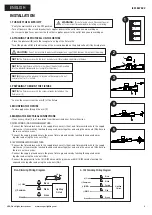
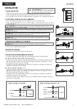
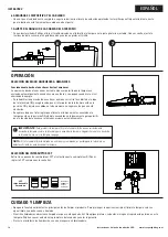
1. TURN OFF THE ELECTRICITY
•
Verify the wall switch is in the OFF position.
•
Turn off power at the circuit breaker that supplies power to the outlet box you are working on.
•
For screw-in type fuses unscrew the fuse that supplies power to the outlet box you are working on.
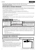
2. ATTACHING THE PHOTOCELL ON THE FIXTURE
•
Place the photocell (B) onto the receptacle on top of the fixture (A)
•
Twist the photocell (B) in the direction of the arrow indicated on the photocell until it locks into place.
3. PREPARING TO MOUNT THE FIXTURE
•
Loosen the screws from the arm (C) of the fixture
4. MOUNTING THE FIXTURE
•
Feed supply wires through the arm (C)
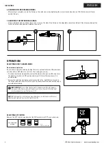
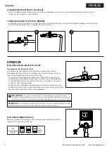
5. MAKING THE ELECTRICAL CONNECTIONS
•
If necessary, strip 3/8 in. of insulation from the junction box or fixture (A) wires.
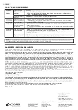
ON/OFF WIRING (NON DIMMING) METHOD:
•
Connect the fixture black wire to the supply black wire ((+) line), and fixture white wire to the supply
white wire ((-) common) by twisting the exposed wires together and using the wire nuts (AA). Ensure
there are no loose wires.
•
Connect the supply ground wire to the green fixture ground wire by twisting the exposed wires
together and using the wire nuts (AA)
0-10V DIMMABLE WIRING METHOD:
•
Connect the fixture black wire to the supply black wire ((+) line), and fixture white wire to the supply
white wire ((-) common) by twisting the exposed wires together and using the wire nuts (AA). Ensure
there are no loose wires.
•
Connect the supply ground wire to the green fixture ground wire by twisting the exposed wires
together and using the wire nuts (AA).
•
Connect the purple wire to the (V+) DIM wire and the pink wire with (V-) DIM wire by twisting the
exposed wire together and using the wire nuts (AA).
INSTALLATION
OFF
ON
OFF
ON
OFF
ON
OFF
ON
B
A
NOTE:
The fixture comes with the twist-lock photocell (B) provided separately in the box.
NOTE:
The fixture comes with the screws already installed on the
fixture arm (C)
NOTE:
The light fixture will not work without the photocell inserted
into the photocell receptacle as it completes the circuit.
NOTE:
Make sure the photocell is locked on the receptor. Do not
over rotate after it is locked.
1
2
3
4
5
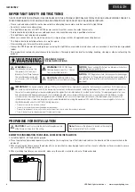
WARNING:
Risk of electric shock. Disconnect power
at fuse or circuit breaker before installing or servicing.
CAUTION:
Do not try to rotate the photocell receptacle on top of the fixture as it may twist the wiring.
(+) Line
Black
White
Lighting
Fixture
Green
(-) Common
Ground
3/8 in.
Non-Dimming Wiring Diagram
(+) Line
Black
White
Lighting
Fixture
Green
(-) Common
Purple
(+)DIM V+
Pink
(-)DIM V-
Ground
0−10V Dimming Wiring Diagram


