Hallman UP60 Скачать руководство пользователя страница 8

8

ELECTRICAL CONNECTION

The appliance shall be connected to a single phase electric line rated at 120/208Vac or 
120/240Vac and 60Hz frequency. 
The appliance is equipped at the factory with a flexible hose . Inside the flexible hose you have 
4 cables: grenn cable must be connected to the ground, white cable (NEUTRAL), red en black 
cables: supply wire (L1 – L2).  Check the electrical schetch available at the bottom  in our in-
structions booklet
Electric power absorption of each model are shown in the Electrical and Gas Power Table en-
closed.
Before connecting the appliance to the electric network, follow the instructions below:
1.  fuse and electric feeding installation of your home must support the load of the appliance (see registration label).
2.  Power supply system must have an e

  cient earth plate.

3.  The outlet or multiple-switch, with a minimum1/8” (3mm) contact opening, has to be easily reached once the 

appliance has been installed.

The appliance is supplied without outlet: you need a normal one proper for the electric load. 
The power supply cable should not reach a 120°F temperature above the one surrounding.

GAS CONNECTION

All gas connections must be made according to national and local codes. This gas supply (ser-
vice) line must be the same size or grater than the inlet line of the appliance. This range uses a 
½”NPT inlet. Sealant on all pipe joints must be resistive to LP gas.

1. 

Manual Shut-o

  Valve: This installer-supplied valve must be installed in the gas service line ahead of the appliance 

in the gas stream and in a position where it can be reached quickly in the event of an emergency. The manual 
shut-o

  valve shall be installed properly in order to be accessible when appliance is installed in de

fi

 nitive position. 

In Massachusetts: A ‘T’ handle type manual gas valve must be installed in the gas supply line to this appliance.

2. Pressure Regulator 
1.  All heavy duty, commercial type cooking equipment must have a pressure regulator on the incoming service line 

for safe and e

  cient operation, since service pressure may 

fl

 uctuate with local demand. The pressure regulator is 

supplied separately with the appliance; regulator has two female threads ½” NPT; it shall be installed properly in 
order to be accessible when appliance is installed in de

fi

 nitive position.

2.  This range can be used with Natural or LP/Propane gas. It is shipped from the factory adjusted for use with natural 

gas. The ori

fi

 ce hoods must be screwed snug when LP/Propane gas is used(see LP/Propane conversion).

3.  The appliance, its individual shut-o

  valve, and pressure regulator must be disconnected from the gas supply 

piping system during any pressure testing of that system at pressure is in excess of 1/2psig(3.45kPa).

4.  The appliance must be isolated from the gas supply piping system by closing its individual manual shut-o

  valve 

during any pressure testing of gas supply piping system at test pressures equal to or less than 1/2psig(3.45kPa).

3. Flexible Connections:
1.  If the unit is to be installed with 

fl

 exible couplings and/or quick disconnect 

fi

 ttings, the installer must use an heavy 

duty, AGA design-certi

fi

 ed commercial 

fl

 exible connector of at least ½”(1.3cm)ID NPT(with suitable strain relieves) 

in compliance with ANSI Z21.41 and Z21.69 standards.

2.  In Massachusetts: The unit must be installed with a 36” (3-foot) long 

fl

 exible gas connector.

3.  In Canada: CAN 1-6.10-88 metal connectors for gas appliances and CAN 1-6.9M79 quick disconnect device for 

use with gas fuel.

CAUTION: Leak testing of the appliance shall be conducted according to the manufacturer’s instructions. Before placing the 
oven into operation, always check for leaks with a soapy water solution of other acceptable method. DO NOT USE AN OPEN 
FLAME TO CHECK FOR LEAKS!

Содержание UP60

Страница 1: ...15 32 35 53 64 H UP76 29 7 8 W x 23 5 8 D x 33 15 32 35 53 64 H UM76 29 7 8 W x 27 9 16 D x 34 1 4 36 20 32 H UP90 UPD90 35 7 16 W x 23 5 8 D x 33 15 32 35 53 64 H UM90 35 7 8 W x 27 9 16 D x 34 1 4 3...

Страница 2: ...urer will not be responsible for any damage to property or to persons caused by incorrect installation or improper use of the appliance The manufactured reserves the right to make changes to its produ...

Страница 3: ...ce do not touch grates burner caps burner bases or any other parts in proximity to the flame These components may be hot enough to cause burns Never leave this appliance unattended when in use Boilove...

Страница 4: ...al shuto valve during any pressure testing of the gas supply piping system at test pressure equal to or less than psi 3 5kPa For use with a pressure regulator The regulator supplied must be used with...

Страница 5: ...D 2 Secure the foot cover D with three bolts the three whashers and the three nuts B into the bracket C which is positioned at the rear of the kitchen Fig 1c 1 Screw partially bolt F into the base fee...

Страница 6: ...s 15 64 6mm on the wall at the measured dimension plus 5 32 4mm The two anti tip have to be placed close to the side of the range location recommended dimension is 1 25 4mm from the sides 4 Fix the tw...

Страница 7: ...e CANNOT be installed directly adjacent to sidewall as cabinets appliances or other side vertical surface above 36 20 32 high There must be a minimum of 5 side clearance 3 Within the side clearance to...

Страница 8: ...manual gas valve must be installed in the gas supply line to this appliance 2 Pressure Regulator 1 All heavy duty commercial type cooking equipment must have a pressure regulator on the incoming serv...

Страница 9: ...S Any conversion required must be performed by your dealer or a qualified licensed plumber or gas service company Please provide the service person with this manual before work is started on the range...

Страница 10: ...ifice must be fully screwed in To convert the regulator Fig 6 and Fig 7 for use with the other gas different from which one it is pre arranged it is enough perform the following operations 1 Unscrew b...

Страница 11: ...dj Small Solid Top Bur ner NATURAL A 8500 130 2100 5 Adj OVEN 60 NATURAL A 11500 155 4 GRILL 60 NATURAL A 9000 140 OVEN 70 NATURAL A 15000 180 4 GRILL 70 NATURAL A 13500 165 OVEN 90 1 burner NATURAL A...

Страница 12: ...lack of air it is irregular with yellow streaks Move sleeve R backward C Normal flame its colour is light blue Figure 8 Figure 9 Figure 10 B1 Burner in the oven 1 Remove the bottom shelf of the oven...

Страница 13: ...y to be carried out by an authorised person To replace parts such burners valves and electric components the hotplate must be removed from the bench top by releasing the attachment hooks loosening the...

Страница 14: ...ll the small door towards you until it uncouples from the connection To reassemble the door proceed in inverse order taking care to insert the two guides F correctly OVEN DOOR The oven door is compose...

Страница 15: ...en light is not working properly disconnect the appliance from the mains remove the protection glass of the lamp and replace it Fig 20 Take care that lamp must be suitable for working at high temperat...

Страница 16: ...oven has completely cooled down clean it referring to the paragraph Cleaning and care IMPORTANT correct positioning of the brass flame distributor d Fig 21 is very important For this purpose ensure t...

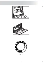
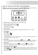
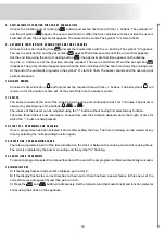
Страница 17: ...17 Figure 24 Figure 25 Figure 23...

Страница 18: ...ously The time is set by pressing the buttons Any previously set programmes will be automatically cancelled 6 MANUAL FUNCTION This function is set by pressing the cooking time and end of cooking butto...

Страница 19: ...set At the end of this time the buzzer sounds 11 BUZZER The buzzer sounds at the end of the cooking time function and continues to buzz for 7 minutes The buzzer is silenced by pressing any of the butt...

Страница 20: ...perate the turn spit on 35 45 64 ovens 7 Upper lower elements and fan A fast intensive form of cooking suitable for a variety of dishes It replaces the turn spit and can be used for baked fish braised...

Страница 21: ...as Then turn the knob G and select the desired temperature The ignition of the oven burner takes place automatically after a few seconds If this does not happen switch o and repeat the operation 2 Ele...

Страница 22: ...USE THE GAS OVEN WITH GAS GRILL 1 Selecting ventilated gas function Turn the knob A and select the ventilated cooking gas Then turn the knob G and select the desired temperature The ignition of the ov...

Страница 23: ...s can be cooked at the same time Fig 33 If necessary it can be used as a handy top providing ample space for resting pots and pans CLEANING THE COUP FEU PLATE The hotplate should be cleaned while stil...

Страница 24: ...for this type of Oriental cooking is available as an optional accessory Some models are supplied with the spatula shown in Figure 35 which is useful both for cooking and for cleaning the plate CLEANI...

Страница 25: ...and temperature of the food the type of gas and of course your own personal taste Figure 39 40 41 COOKING TABLE purely indicative values after 10 preheating with the burner at maximum power Knob posit...

Страница 26: ...goose 320 370 2 3 120 160 Roast duck 340 360 2 3 100 160 Rare roast beef 360 2 3 70 90 FISH 320 360 2 3 15 25 CAKES Fruit cake 360 390 2 40 50 Plain square cake 360 375 2 40 45 Brioches 340 360 2 40...

Страница 27: ...oast goose 440 2 3 60 70 Roast duck 450 500 2 3 45 60 Rare roast beef 450 500 2 3 40 45 FISH 390 440 1 2 15 25 CAKES Fruit cake 440 2 35 40 Plain square cake 350 390 2 50 60 Brioches 350 390 2 25 30 S...

Страница 28: ...MP UP150SVG UP150FVG UP150FSVG UM150SVG UM150FVG UM150FSVG UP150SVGG UPD1207VGG UPD120FVGG UPD120SVGG UP150SVGG UP150FVGG UP150FSVGG UM150SVGG UM150FVGG UM150FSVGG UQDC1207VGG UQDC120FVGG UQDC120SVGG...

Страница 29: ...29 MULTIFUNCTION MODELS ONLY Big Solid Top Burner...

Страница 30: ...30 UP90MP...

Страница 31: ...31 UP90VG...

Страница 32: ...32 UPD100FMP...

Страница 33: ...33 UPD90VG...

Страница 34: ...34 UP120SMP...

Страница 35: ...35 UP120VG...

Страница 36: ...36 UP150MP...

Страница 37: ...37 UM150SVG...

Страница 38: ...38 UP90VGG...

Страница 39: ...39 UPD90VGG...

Страница 40: ...40 UP120VGG...

Страница 41: ...41 UP150SVGG...

Страница 42: ...6VG 2 3 1 1 1 1 72500 3 6 UPD F L W N S 906VGG 2 3 1 1 1 1 1 81500 1 9 UPD F L W N S 906MP 2 3 1 1 1 61000 5 5 UQDC90WVG 1 2 1 1 1 1 1 65500 3 6 UQDC90WVGG 1 2 1 1 1 1 1 1 74500 1 9 UQDC90WMP 1 2 1 1...

Страница 43: ...G 1 3 2 1 1 1 1 1 108500 2 1 UPS F L W N S 120FMP 1 3 2 1 1 1 80000 5 7 UPS F L W N S 120SVG 1 2 1 1 1 1 1 1 77500 4 5 UPS F L W N S 120SVGG 1 2 1 1 1 1 1 1 1 91000 2 1 UPS F L W N S 120SMP 1 2 1 1 1...

Страница 44: ...D F L W N S 906DVG 2 3 1 1 1 1 72500 3 6 UPD F L W N S 906DVGG 2 3 1 1 1 1 1 81500 1 9 UPD F L W N S 906DMP 2 3 1 1 1 61000 5 5 UQDC90PDWVG 1 2 1 1 1 1 1 65500 3 6 UQDC90PDWVGG 1 2 1 1 1 1 1 1 74500 1...

Страница 45: ...GG 1 3 1 1 1 1 1 1 1 108500 2 1 UPS F L W N S 120FDMP 1 3 1 1 1 1 1 80000 5 7 UPS F L W N S 120SDVG 1 2 1 1 1 1 1 1 77500 4 5 UPS F L W N S 120SDVGG 1 2 1 1 1 1 1 1 91000 2 UPS F L W N S 120SDMP 1 2 1...

Страница 46: ...1 108500 1 9 UP F L W N S 120FDDMP 1 3 2 1 1 1 80000 5 5 UM120FDDMP_UMT120FDDMP 1 3 2 1 1 1 80000 5 5 UPD F L W N S 1207DDVG 1 3 2 1 1 1 1 91500 5 5 UPD F L W N S 1207DDVGG 1 3 2 1 1 1 1 1 100500 3 8...

Страница 47: ...VGG_UM T CA 150SDDVGG 1 3 2 1 1 1 1 1 106500 3 8 UP F L W N S 150SDDMP 1 3 2 1 1 1 78000 7 4 UM150SDDMP_UM T CA 150SDDMP 1 3 2 1 1 1 78000 7 4 UP F L W N S 150FDDVG 1 3 2 1 1 1 1 105500 6 2 UM150FDDVG...

Отзывы: