background image

17

2022

Innovative Vehicle Solutions

DIAG++

Operator‘s Guide

DIAG++

3

12

13

11

10

9

8

2

1

4

5

6

7

14

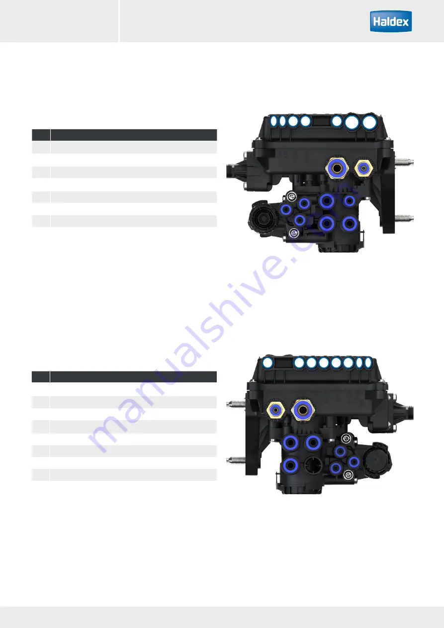
No. Description

1

ISO 7638 PWR-A

2

ISO 12098 / PWR-B

3

S-CAN

4

H-CAN

5

T-CAN

6

Sensor S2A

7

Sensor S1A

No. Description

8

AUX 5

9

AUX 4

10

AUX 3

11

AUX 2

12

AUX 1

13

AUX 0

14

Sensor S2B

15

Sensor S1B

15

Premium 2M EBS connections

Содержание DIAG++

Страница 1: ...Innovative Vehicle Solutions OPERATOR S GUIDE ...

Страница 2: ...t the manual will be used as a teaching aid following supervision of a Haldex engineer or a reminder of the correct procedure for operating Haldex DIAG software Use appropriate spare parts documentation when obtaining spare parts Use only genuine Haldex parts in repairs Due to continuous development the right is reserved to alter the specification without notice No legal rights can be derived from...

Страница 3: ...nts Installation Introduction 6 Installation 7 Starting DIAG 12 Settings 13 EBS Operation ECU connections 16 Home screen 24 Basic diagnostics service menu 27 Setting parameters ECU configuration 33 Auxiliary operation 43 EB Soft Docking 79 End of line test EOLT 86 ...

Страница 4: ...4 Innovative Vehicle Solutions 2016 4 Innovative Vehicle Solutions 2022 Operator s Guide DIAG ...

Страница 5: ...5 2016 Innovative Vehicle Solutions INSTALLATION Introduction 6 Installation 7 Starting DIAG 12 Settings 13 5 2022 Innovative Vehicle Solutions Operator s Guide DIAG ...

Страница 6: ...SB PC Interface dongle allows communications between a standard PC and the EBS ECU Connections to the USB PC Interface dongle are made through a cable connecting to a USB port on the computer and another cable connecting the diagnostic interface to the ECU The vehicle parameter data is stored inside the ECU It will remain intact even after electrical power is removed from the EBS Note The USB PC I...

Страница 7: ...nt RAM 256 megabytes Hard drive 30 megabytes free MS Window 10 In addition to the above a USB port is required to connect to the USB PC Interface dongle Downloading DIAG The latest DIAG version software can be downloaded from the Findex section of the Haldex web site To download follow Go to http www haldex com Click on Trailer Guide Application Click on service Download software Follow installati...

Страница 8: ...Create a desk top short cut to Haldex Diagnostics exe in publish directory of unzipped DIAG In addition to the application folders the following folder structure is added to your computer when DIAG first runs On Windows 10 the Haldex folder will be located in C Users Public Public Documents Haldex DIAG DTC reports ECU AUX only setup files ECU Modification records ECU Programming records ECU setup ...

Страница 9: ...lling the hardware The DIAG interface kit is comprised of the USB PC Interface Dongle together with its connecting cables and a transit case 950 800 909 Interface kit Part number Description 815 023 001 USB PC Interface DIAG 042 707 309 USB cable 950 800 912 Diagnostic cable kit Part number Description 814 036 001 ECU PC Interface cable 6 5 m 844 511 465 EB 4 0 CAN to PC interface cable 6 5m 815 0...

Страница 10: ...fied and smoothed or a tractor unit The LED light on the PC Interface should now be on coloured red If it is not please check your connections and try again PC Interface 815 023 001 844 511 XXX USB cable 042 7073 09 Connect to T CAN or H CAN Connecting to EB 4 0 via ISO 7638 The ECU can be accessed by using the EB ISO diag nostic cable 815018001 Disconnect the ISO 7638 truck to trailer cable and c...

Страница 11: ...ccept the agreement click on next to proceed Software updating Software update now complete Click on finish to proceed Restart your computer to apply these changes Updating the USB dongle software The USB dongle software can be updated to the latest revision The required files have been downloaded along with the DIAG software and can be found here C Program Files Common Files Haldex USB Run the do...

Страница 12: ...icates connection to USB and EB 4 0 EBS Green Indicates data is being transmitted Power up the ECU During the self check procedure the system displays the following functions the trailer EBS warning light comes on and stays on One audible cycle is produced by the EPRV s EBS valves At the same time the LED on the USB dongle will illuminate red green to show that it is communicating with the ECU The...

Страница 13: ...The DIAG options can be selected by clicking on the settings link DIAG only supports EB 4 0 EBS The DIAG software can be configured by the user using the available icons Language not active at the moment General options not active at the moment EOLT settings File paths ...

Страница 14: ...14 Innovative Vehicle Solutions 2016 14 Innovative Vehicle Solutions 2022 Operator s Guide DIAG ...

Страница 15: ... Solutions EBS ECU connections 16 Home screen 24 Basic diagnostics Service menu 27 Setting parameters 33 Auxiliary operation 43 Soft Docking 79 End of line test EOLT 86 15 2022 Innovative Vehicle Solutions Operator s Guide DIAG ...

Страница 16: ...socket assembly 4 ISO 12098 PWR B Optional safety back up cable Super AUX Additional inputs 5 EB Info Centre 6 Sensor assembly 7 Exciter 8 RTR Programmable via DIAG 9 Lift axle Programmable via DIAG 10 Lining Wear System LWS Programmable via DIAG 7 S1B S1A S2B S2A 6 6 6 1 2 3 4 5 10 8 9 6 7 7 7 S1B S1A S2B S2A AUX 0 T CAN H CAN S CAN PWR B PWR A AUX 1 AUX 2 AUX 3 AUX 4 AUX 5 ECU connections ...

Страница 17: ...IAG 3 12 13 11 10 9 8 2 1 4 5 6 7 14 No Description 1 ISO 7638 PWR A 2 ISO 12098 PWR B 3 S CAN 4 H CAN 5 T CAN 6 Sensor S2A 7 Sensor S1A No Description 8 AUX 5 9 AUX 4 10 AUX 3 11 AUX 2 12 AUX 1 13 AUX 0 14 Sensor S2B 15 Sensor S1B 15 Premium 2M EBS connections ...

Страница 18: ...urpose output TA Speed lock TPMS lamp AUX 4 AUX 5 Lining wear sensor General purpose input Control line sensor Mechanical height sensor Mechanical height sensor remote External pressure sensor Premium EBS auxiliary operation AUX 0 COLAS Retarder Trailer lamp ILAS E front ILAS E rear AUX power Steer axle lock Service lamp Overload lamp Remote overload lamp Stability lamp ILAS E front manual ILAS E ...

Страница 19: ...19 2022 Innovative Vehicle Solutions DIAG Operator s Guide DIAG H CAN TPMS Soft Docking EB Info Centre PC interface S CAN 1M Slave Premium EBS CAN operation T CAN Telematics Customer PC interface ...

Страница 20: ...ECU Customer specific installation Telematics Customer specific installation ISO12098 C1 C7 C8 C9 C13 5 1 C3 C4 C5 C6 C2 C2 C11 C10 C12 Key Cables Options C1 ISO7638 DIAG Interface PWR A Sensor S1B Sensor S1A COLAS ILASE E ILASE E Lining Wear Sensing Traction help switch S1B S1A S2B S2A AUX 0 T CAN H CAN S CAN PWR B PWR A AUX 1 AUX 2 AUX 3 AUX 4 AUX 5 T CAN T CAN EB Soft Docking TPMS ...

Страница 21: ...SO 7638 diagnostic 815 018 001 C11 PC interface 814 011 001 PC Interface to ISO 7638 diagnostic C12 Dongle USB cable 042 7073 09 Remote PC to DIAG PC Interface C13 Customer specific ECU Customer specific ECU to CAN Y Splitter Item Option description Part No Notes 1 EB 4 0 assembly 842 014 001 Premium with Mobiliser shown 2 ISO 7638 7 pin socket assembly 844 001 XXX ISO 7638 7 pin socket to EB 4 0 ...

Страница 22: ...tem Description Notes 1 EB 4 0 assembly Premium version shown 2 1M Slave assembly 3 EB label 4 ISO 7638 7 pin socket assembly 5 ISO 12098 PWR B Optional safety back up cable 6 Sensor assembly 7 Exciter 8 3M link cable 7 S1B S1A S2B S2A 6 6 6 3 4 1 2 5 6 7 7 7 S1B S1A S2B S2A AUX 0 T CAN H CAN S CAN PWR B PWR A AUX 1 AUX 2 AUX 3 AUX 4 AUX 5 8 ...

Страница 23: ...23 2022 Innovative Vehicle Solutions DIAG Operator s Guide DIAG 1M connections No Description 1 S CAN 2 Sensor A No Description 3 AUX 4 Sensor B 1 2 3 4 ...

Страница 24: ...indow 12 Power source indicator 02 Service options 13 Odometer reading total distance 03 ECU options 14 System information lamp 04 End of line Test EOLT procedure 15 System warning lamp 05 Advanced options 16 Shows active diagnostic trouble codes 06 Settings 17 Animation Not implemented fully yet 07 PC connection port indication 08 EBS connection graphic 09 Chassis number 10 ECU software version n...

Страница 25: ...een display 1 2 5 6 6 5 4 3 7 8 Supply pressure Reservoir P S valve Master ECU Brake Actuator Service pressure 01 Service pressure bar 02 Reservoir pressure bar 03 System supply voltage volts 04 Supply pressure bar 05 Master ECU brake actuator pressure bar 06 Master ECU wheel speed km h 07 Master ECU air suspension pressure bar 08 ISO pressure not implemented yet ...

Страница 26: ...2 Operator s Guide Click on the ECU software version number to display the type of ECU that is connected Click on the interface version number to display the connected dongle data not fully implemented yet Connected ECU and dongle information ...

Страница 27: ...n set in the lamp setting section of the ECU Setup Note If the trailer warning lamp comes on and stays on there are diagnostic trouble codes DTC present which need to be cleared or the system air pressure is below 4 5 bar Click on the Service button on the main screen then Click on the DTC s button to show any active or stored DTC s If there are no DTC s detected the following screen will appear ...

Страница 28: ...ctive stored DTC s If there is no active DTC it will display no active DTC s Any active DTC will be displayed in the Active DTCs section Repair the active DTC and reset the ECU by pressing the Reset ECU button or switch off then on the power to the ECU Any repaired DTC will transfer into the ECU memory i e stored DTC Any stored DTC will be displayed in the Stored DTCs section ...

Страница 29: ...formation dialog is thrown up to indicate the progress When the stored DTC s have cleared click ok button Click on the Back button to return to the service options Or Click on any of the left hand side button links to move to that dialog Reading extended diagnostic codes On active and stored DTC s double click on any DTC Extended DTC screen display ECU clearing the stored DTC ...

Страница 30: ...plied status 11 Stop light power available yes no when fault first occurred 12 Red lamp status on off when fault first occurred 13 Amber Lamp status on off when fault first occurred 14 Service request status active inactive when fault first occurred 15 Lamp fault status on off for this fault 16 Stop light power in use yes no when fault first occured 17 Day of month when available where fault first...

Страница 31: ...y what has been set in the lamp setting section of the ECU Setup Note If the trailer warning lamp comes on and stays on there are DTC s present which need to be cleared as above or the system air pressure is below 4 5 bar When the active DTC s have cleared to stored click ok button Click on the Back button to return to the service options Or Click on any of the left hand side button links to move ...

Страница 32: ...e Vehicle Solutions DIAG 2022 Operator s Guide Viewing DTC information Click DTC information icon to display the DTC information Click on the required DTC for possible causes For example wheel sensor 1A continuity ...

Страница 33: ...ters ECU configuration 3 2 1 5 4 6 7 8 01 Load Load ECU configuration from file 02 Load AUX Data Load ECU AUX configuration from file 03 Read Read ECU configuration 04 Edit Edit ECU configuration 05 Save Save ECU configuration to file 06 Save AUX Data Save ECU AUX configuration to file 07 Program Program ECU configuration 08 Print Print ECU configuration ...

Страница 34: ...uration Edit ECU setup menu Note The following defaults are set as shown below Auxiliaries not used unused Wheel scaling 306 rev km 520 Rdyn mm and 100 no of teeth exciter Lamp sequence on off 5 6 7 4 3 2 1 01 Layout 05 Wheel scale 02 Advanced options 06 Trailer information 03 Load plate 07 Auxiliary information 04 Geometric data ...

Страница 35: ...Slave Twin to be configured from layout drop down Note Users should try to mimic the physical layout of the ECUs Axles when defining the logical layout For example if a 8S4M system on a 4 axle trailer is required with slaves on axle 1 and 2 and the master on axle 3 4 then the logical layout should look like this Layout tab Note all Master Slave Twin layouts are shown as front facing if rear facing...

Страница 36: ...de Power A PWR A connector side EPRV Front facing EBS EBS is mounted in front of the cross beam facing to the front of the trailer S2A S2B S1A S1B 22 21 Trailer King Pin Trailer King Pin Power A connector Power A PWR A connector side Drawing symbol Premium 2M Master EBS rear facing Key EPRV 21 22 2M Master EBS Power A PWRA connector side Mounting stud side 2M Master EBS EPRV Rear facing EBS EBS is...

Страница 37: ... s or a Twin Master layout selections If configured choose correct Slave s Layout Note if Slave s selected then any additional Twin selection is invalid If configured choose correct Twin Layout Note if Twin selected then any additional Slave s selection is invalid Click on the Save configuration button to save the updated settings Twin Slave layout selections Slave layout selections ...

Страница 38: ...ering ISO 1185 24N If box 5 is selected this allows the weight of the trailer to be indicated in the cab if the truck supports this function If box 6 is selected any automatic lift axles will not raise until move away when the lamp goes out It is to enable roller testing of all axles even when unladen Note Use for the UK vehicle test authority If box 7 is selected Master valve on trailer will alwa...

Страница 39: ...entered from a Haldex brake calculation as shown below Example The graph shows the brake demand pressure INPUT values are in relation to the brake delivery pressure OUTPUT values Note If values 6 7 8 and 9 are required see brake calculation example below To enter the values click on Use boxes PP1 Control PP2 Control PP1 Delivery Laden 6 8 7 9 1 60 1 20 3 00 2 60 PP2 Delivery Laden Use Use PP3 Lade...

Страница 40: ...ar Brake press unladen bar 1 2 3 1150 1150 1150 0 60 0 60 0 60 1 75 1 75 1 75 Bag press laden bar Brake press laden bar 4 30 4 30 4 30 0 00 0 30 1 20 2 60 5 90 bar 0 00 0 30 1 20 2 60 5 90 bar 0 00 0 30 1 20 2 60 5 90 bar Axle load laden Kg 8000 8000 8000 control pr pm P0 PD 0 30 0 70 1 60 3 00 6 50 bar 2 5 4 3 9 7 8 6 1 12 11 10 Haldex brake calculation example ...

Страница 41: ...rake calculation as shown below Brake calculation example Master ECU RAG Input data for the EBS Modulator EB Axle control pr pm 6 50 bar Axle load unladen Kg Bag press unladen bar Brake press unladen bar 1 1700 0 55 2 10 Bag press laden bar Brake press laden bar 3 50 0 00 0 40 6 85 bar Axle load laden Kg 9000 control pr pm P0 PD P3 0 40 0 70 6 50 bar RAG 1 2 5 4 3 12 11 10 ...

Страница 42: ...values entered from a Haldex brake calculation as shown below Input data for the EBS Modulator EB Axle control pr pm 6 50 bar Axle load unladen Kg Bag press unladen bar Brake press unladen bar 1 2350 0 70 2 10 Bag press laden bar Brake press laden bar 5 00 Axle load laden Kg 10000 control pr pm P0 PD P1 P2 P3 FAG 0 20 0 70 2 00 2 50 6 50 bar 0 00 0 50 1 40 2 50 6 85 bar 12 11 10 1 2 5 7 6 8 4 3 9 ...

Страница 43: ...y current for each channel Dig I P AUX 0 Digital monitor input Both red channel pin 1 and yellow channel pin 3 can be used to monitor a state of change input B or B Dig I P AUX 0 3 Digital monitor input Red channel pin 1 can be used to monitor a state change input B or B Ana I P AUX 1 3 Analogue input on yellow channel pin 3 can be used to measure voltage input Ana I P AUX 4 5 Analogue input Analo...

Страница 44: ...urpose output TA Speed lock TPMS lamp AUX 4 AUX 5 Lining wear sensor General purpose input Control line sensor Mechanical height sensor Mechanical height sensor remote External pressure sensor Premium EBS auxiliary operation AUX 0 COLAS Retarder Trailer lamp ILAS E front ILAS E rear AUX power Steer axle lock Service lamp Overload lamp Remote overload lamp Stability lamp ILAS E front manual ILAS E ...

Страница 45: ...the Edit button to setup the auxiliary configuration The following screen will appear The screen shows the various auxiliary connections that can be used i e AUX 0 to 3 4 and 5 Clicking on the required AUX down arrow displays a listing of options that can be selected Example AUX 1 options expanded ready for selection ...

Страница 46: ...t can be used as follows Red wire 5 volt supply Yellow wire Analogue input Black wire system ground Programming Standard AUX using DIAG Programming of AUX 4 and AUX 5 on EB 4 0 is only possible using DIAG software The AUX configuration screen shows the various auxiliary connections that can be used AUX 4 Analogue input AUX 5 Analogue input Clicking on the drop down arrow displays a list of options...

Страница 47: ...utput The twin inputs or outputs of AUX 0 to AUX 3 are colour coded red and yellow within the DIAG software These colours then match the twin colour identifiers on the cables Premium auxiliary connection cables To use the full auxiliary twin functionality of the Premium AUX the following cables can be used 844 301 XXX Bare ended cable for customers to fit their own connectors Gen3 Equivalent 814 0...

Страница 48: ...n the EB 4 0 software Gen3 Equivalent 814 039 001 844 342 001 M F F Splitter Premium Aux meaning each cable can be programmed individually in the EB 4 0 software Gen3 Equivalent N A 844 321 XXX DIN 72585 Socket connection for ILAS COLAS etc Gen3 Equivalent 814 012 2XX 814 027 001 Male to female to female 2x2x2 way 3 5 6 NEW Yellow marker Red marker ...

Страница 49: ...guration screen shows the various aux iliary connections that can be used AUX 0 Red yellow AUX 1 Red yellow AUX 2 Red yellow AUX 3 Red yellow AUX 4 AUX 5 Super AUX Clicking on the drop down arrow displays a list of op tions that can be selected on that auxiliary Premium AUX example AUX 2 red AUX COLAS AUX 2 yellow AUX ILAS E front AUX 3 red AUX Service lamp AUX 3 yellow AUX Stability lamp ...

Страница 50: ...onnector includes an additional three digital inputs and 24 V signal supply only use the 24 V signal supply for the Super AUX control switches The control inputs can be linked to any auxiliary feature and this allows very sophisticated applications to be realised in a very simple manner Some examples for controllable auxiliary features are traction support and or steer axle lock and or EBD Electri...

Страница 51: ... 12098 Gen3 Equivalent 814 004 3XX 844 211 XXX 2 core Super Aux to DIN 72585 Plug to ISO 12098 844 242 XXX 6 core Super Aux to 4 core DIN 72585 Plug to ISO 12098 and 2 core DIN 72585 Socket to Trailer Lift Axle Switch Gen3 Equivalent 814 029 2XX 844 201 XXX Bare ended 24N cable with Warning Lamp to ISO 12098 8 8 9 NEW ...

Страница 52: ...en shows the various auxiliary connections that can be used AUX 0 Red yellow AUX 1 Red yellow AUX 2 Red yellow AUX 3 Red yellow AUX 4 AUX 5 Super AUX Clicking on the drop down arrow activates the Super AUX option Configuring Super AUX Click on the Modify button to configure the Super AUX inputs Super AUX option Super AUX drop down arrow Super AUX option is selected Super AUX modify button ...

Страница 53: ...s than and equal to selected km h Greater than selected km h Click on the Cancel button to cancel with no modifications Click on the OK button to exit and keep the modifications Inputs A B and C can also be renamed to their intended activation input e g door The required input combination can be achieved by using the drop down boxes for The input signal e g door The activation level i e high or lo...

Страница 54: ...ration Time COLAS solenoid is energised default 5s ON speed The output to the COLAS will be switched on de fault 15 kph OFF speed The output will be switched off either when the vehicle decelerates below the off speed or when du ration has been exceeded whichever happens first default 0 kph Note By setting the duration to 0s this now becomes a speed signal and an on and off speed has to be set Dep...

Страница 55: ...OR AUX output will change status if COLAS function OR any related input is active AND AUX output will change status if COLAS function AND all related inputs are active COLAS output functions 24 V Standard output COLAS function AND OR logic HIGH 24 V to solenoid otherwise 0 V 0 V Inverted output COLAS function AND OR logic HIGH 0 V to solenoid otherwise 24 V Note the output level can be adjusted in...

Страница 56: ...tion is set to 0 then the solenoid will switch on after crossing the on speed threshold without a time limitation It will only switch off when the off speed is crossed You can use this setting e g to drive an external device that needs power and a speed signal that is always supplied on the yellow wire of the 3 core AUX cable of AUX 1 e g 0 s 15 kph 10 kph 2 Movement detection with time limitation...

Страница 57: ...ypes of ILAS E ILAS E Auto front rear Supported on AUX 0 1 2 3 ILAS E Manual front rear Supported on AUX 1 2 3 The required ILAS E type is selected from the desired AUX drop down Further configuration of the ILAS E selected can be done by clicking the ILAS E configuration MODIFY button ...

Страница 58: ...ns DIAG 2022 Operator s Guide Then choose relevant tab for the ILAS E type configured as shown below Please note there are differences in the configuration options for the different ILAS E types Front Manual Front Manual Rear Rear ...

Страница 59: ...tes for all ILAS E types 1 Raising happens fully automatically below the raise threshold 2 Dropping happens fully automatically above the drop threshold 3 If front and rear lift axles are configured the one with the higher raise threshold raises first 4 If front and rear lift axles are configured the one with the lower drop threshold drops first Raise speed If the option raise with speed is set fo...

Страница 60: ...ual lower A 24 V signal switch on the yellow wire of the 3 core AUX cable is required Auto raise Auto lower Drop The load where the ILAS solenoid is de energised causing the axle to drop default 90 Raise The load where the ILAS solenoid is energised causing the axle to raise default 50 Sensor configuration Disables the wheel speed signal when a sensed axle is raised default not sensed Note Raise w...

Страница 61: ...ways to set this higher value will be used For all ILAS E types 1 In the ECU Configuration dialog Layout tab select lift axles when vehicle moved then all lift axles will not raise until vehicle has first exceeded 7 kph after ignition on Additionally for ILAS E Auto Only 1 AND OR in ILAS E Configuration dialog select raise with speed option drop with speed becomes available and can be selected if ...

Страница 62: ...unctions can be controlled extended by several inputs These inputs don t control the output directly as in other cases In this case inputs are logically connected to the yellow wire of the AUX port With the yellow wire you can control manual lift axles and traction support and you get the same result if you use one or more of the Super AUX or GPI inputs If you use automatic lift axles only the inp...

Страница 63: ...splayed above 130 to ask the user to check the design weights for the remaining axle s as the legal limit is 130 of design weight Traction Speed Limit The Traction Help axle will drop once the vehicle speed increases above the value default 30km h A warning icon is displayed above 30km h to indicate that this is above the legal limit Two counts are provided to optionally provide Lift Axle Position...

Страница 64: ...s been accepted there is a 30 second damping delay on accepting any subsequent activation to avoid the lift axle dropping before it is fully raised Allow Disable Lift Axle If ticked then system always assumes switch is momentary and will disable drop all lift axles until the system is next re powered ignition off Disable Lift Axles Shutdown by Brake Pedal If ticked this disables the dropping of an...

Страница 65: ...e an in verted AUX output Example automatic steer axle lock function high or reversing high e g Super AUX B Result In both cases you get 0 V output to lock Important Only use one of the inversion options Otherwise you may get unexpected results Special case for speed setting If you set both speeds to 0 the function only locks depending on the lift axle position or related control inputs Speed no l...

Страница 66: ...ion AND OR logic HIGH 24 V to solenoid otherwise 0 V 0 V Inverted output Function AND OR logic HIGH 0 V to solenoid otherwise 24 V The output level can be adjusted independently of input use Possible inputs Super AUX A B C custom general purpose input GPI AUX 4 5 Service lamp settings information Function can be controlled extended by several inputs OR AUX output will change status if function OR ...

Страница 67: ... 24 V Standard output Function AND OR logic HIGH 24 V to solenoid otherwise 0 V 0 V Inverted output Function AND OR logic HIGH 0 V to solenoid otherwise 24 V The output level can be adjusted independently of input use Possible inputs Super AUX A B C custom general purpose input GPI AUX 4 5 Stability lamp settings information Function can be controlled extended by several inputs OR AUX output will ...

Страница 68: ... HIGH 0 V to solenoid otherwise 24 V The output level can be adjusted independently of input use Possible inputs Super AUX A B C custom general purpose input GPI AUX 4 5 Traction assist TA settings information Function can be controlled extended by several inputs OR AUX output will change status if function OR any of the related inputs are active AND AUX output will change status if the function A...

Страница 69: ...rakes independently Options Load Transfer lift Load Transfer Settings Transfer Above this is the overall percentage load above which automatic Load Transfer is allowed Load Target this is the target percentage load on the front centre axles after transfer has taken place the Load Target Tolerance Tag Axle Minimum Pressure Load transfer may stop before the Load Target is reached in order to protect...

Страница 70: ...econds is a manoeuvring request and will use the available Load Transfer hardware to temporary minimize the wheelbase Load Target is changed to the Traction Overload Limit Extra Lift Axle Data Manoeuvring is cancelled when Traction Speed Limit Extra Lift Axle Data is reached or by a further short activa tion of the switch Note Load Transfer is effectively the opposite to traction assist ...

Страница 71: ... are active You can connect simple switches or any type of 5 V sensor pressure sensor 0 8 bar M16 x 1 5 is available from Haldex AUX cable colours and function Red Output 5 V supply Black B Yellow Input signal analog 0 24 V You can use the output high low to control other auxiliaries Application examples 1 Traction help for lift axle by switch mounted on the trailer and or in the cab 2 Monitoring ...

Страница 72: ...e the deflection is entered the user must set the lever length to between the allowed lever length range The allowed lever length range varies depending upon the deflection Examples A deflection of 20 mm will allow a lever length range of 100 to 151 mm as seen in the picture A deflection of 55 mm will allow a lever length range of 276 to 320 mm Once the lever length is set the user then enters the...

Страница 73: ...appear Click on box electric brake demand to select installation Select default settings Load the default settings for these three known applications Modifications are allowed but then it is no longer a DIAG default setup Street laying machine Bogie inter lock Extendable drawbar trailer Cab warning Lamp ECE R 13 Driver can be informed by ABS warning lamp if EBD active None Yellow lamp Red lamp buz...

Страница 74: ...h under special conditions big gradient during street building To achieve this the pneumatic demand pressure must be higher than the current EBD demand pressure for a short period of time Electric brake demand information By default the EBD feature is inactive and must be controlled by external input switch The following inputs can be used GPI4 AUX 4 connected to a switch yellow core as signal inp...

Страница 75: ...the default value of a tire size of 306 revs km 520 Rdyn dynamic rolling radius mm with a 100 tooth exciter installed This value covers tire sizes from 19 5 to 22 5 and sets the correct ABS function and odometer of the system Note If the tooth number is not 100 the wheel scale factor on the Info Centre will read a different value Click on the Save configuration button to accept Wheel scale tab ...

Страница 76: ...den 9000 Kg This information is stored in the ECU and can be printed out on the end of line test report and load plate Click on the Save configuration button to accept Geometric data Click on the ECU button then click on the Geometric data tab to open the Geometric options From here the user can enter the following vehicle data Configuration Lift axle position Wheel base The EB transmits Geometric...

Страница 77: ...S with same configuration by clicking on Load ECU configuration from file button and selecting the relevant dpf file then programming that configuration into the EB 4 0 EBS Programming the ECU In ECU configuration dialog click on Program ECU configuration button This will start the programming of the configuration to the ECU The configuration can be obtained from a loaded dpf file or setup manuall...

Страница 78: ...to print the load plate report Print label using Haldex blank label 028 5301 09 Use laser printer only and refer to manufacturers information on printing a A5 size paper After installation spray on a clear lacquer or a hard varnish to protect the printed surface Example label for a semi or centre axle trailer Click on the Back button to return to the ECU configuration options ...

Страница 79: ...ick EB Soft Docking installed How to check if EB Soft Docking is installed Step 1 Turn on the power to the EB 4 0 Open DIAG select ECU configuration Step 2 Read ECU configuration then select ECU Edit configuration Step 3 Select Aux tab Step 4 Select CAN Bus tab Step 5 Observe the EB Soft Docking tick box ...

Страница 80: ...odify button Step 6 Select Reset EB Soft Docking to Plug and Play box Step 7 Click on OK tick to save changes and exit this dialog Step 1 Turn on the power to the EB 4 0 Open DIAG select ECU configuration Step 2 Read ECU configuration then select ECU Edit configuration Step 3 Select Aux tab Step 4 Select CAN Bus tab ...

Страница 81: ... made Step 9 Programme the changed configuration into the EB 4 0 ECU Step 11 Select OK to send data to ECU Step 12 Sending data screen Click OK when finished Step 13 Check using DIAG that the EB Soft Docking has now been removed box unticked Step 10 Remove EB Soft Docking CAN BUS cable from EB 4 0 ECU H CAN to EB Soft Docking cable ...

Страница 82: ...tep 4 Check installation using DIAG Step 5 Open DIAG check that no DTC s are shown How to install a 3 sensor 1 x yellow 2 x green EB Soft Docking system with sensor offsets using DIAG Step 9 Observe the EB Soft Docking tick box Step 10 Select Modify button Step 6 If no DTC s are shown read ECU configuration then select ECU Edit configuration Step 7 Select Aux tab Step 8 Select CAN Bus tab ...

Страница 83: ... DIAG Step 12 Ensure that the CAN Bus Termination box is selected Note the CAN Bus termination shall always be selected unless otherwise advised by Haldex Step 13 Select Help button for additional information Step 11 Check that the number of sensors is correct ...

Страница 84: ...equired go to step 16 Step 15 Proceed to EB Soft Docking EOLT Step 16 Adjust channel values to sensor installation offset Offset example 1 Both channels the same value Offset example 2 Both channels are different values Step 17 Click on OK tick to save changes and exit this dialog Step 18 Important Click Save configuration button to save the changes made ...

Страница 85: ... Innovative Vehicle Solutions DIAG Operator s Guide DIAG Step 19 Programme the changed configuration into the EB 4 0 ECU Step 20 Select OK to send data to ECU Step 21 Sending data screen Click OK when finished ...

Страница 86: ...T dialog EOLT options a Press Start EOLT button to commence EOLT b Press Load from ECU button to load the ECU configuration prior to starting EOLT c An existing EOLT file can be opened eol by clicking the Load EOLT button View print only d Press Print EOLT button to print out EOLT results e Press Save EOLT button to save EOLT results to a file eol ...

Страница 87: ... return to return to the previous dialog Click on the Next button to start the EOLT Note During the EOLT procedure the cab trailer warning lamp will flash to indicate the EOLT is in progress The screen display as shown below is relevant to a Master 2S 2M system Sensor tests This full sensor test is optional as the sensors will also be tested during the Sensor modulator tests Procedure Rotate each ...

Страница 88: ...88 Innovative Vehicle Solutions DIAG 2022 Operator s Guide Continue icon needs to be pressed to continue test Next icon only becomes active when test has completed ...

Страница 89: ...n of the dialog e g S1A S2A S1B S2B SL0A SL0B for this example shown Result section Yellow indicates wheel has moved Green indicates test passed Red indicates test failed S1A test passed If the moving wheel is successfully braked the S1A test will pass and move onto the next wheel to be tested Wheel speed detected moving blue bar Moving wheel yellow indication The screen display as shown is releva...

Страница 90: ...lly braked the S2A test will pass and move onto the next configured sensor in the sequence S2A test started Manually rotate wheel S2A at 1 revolution in 2 seconds Failed test If any of the Sensor modulator test fails check the following Correct testing sequence Rotating the wrong wheel Incorrect wiring Incorrect piping Continue icon needs to be pressed to continue test ...

Страница 91: ...91 2022 Innovative Vehicle Solutions DIAG Operator s Guide DIAG Repeat the Sensor modular test for all the programmed ECU sensors Next icon only becomes active when test has completed ...

Страница 92: ... actual pressures Master measured at the EPRV are displayed above the P21 and P22 result icons The actual pressures 3M Slave0 if present measured at the EPRV are displayed above the Slave0 P2 result icon The actual pressures 4M Slave1 if present measured at the EPRV are displayed above the Slave1 P2 result icon Result section Yellow indicates test started Green indicates test passed Red indicates ...

Страница 93: ...The example shows the screen as for a 2M side by side installation For 3M two screens appear 3M Master and 3M Slave0 For 4M three screens appear in sequence 4M Master and 4M Slave0 and 4M Slave1 Next icon only becomes active when test has completed Note Before this test a warning screen may appear Make sure that there is the required air pressure in the reservoir to carry out the test Failure resu...

Страница 94: ...e off and norm buttons are highlighted toggle between the on and off The norm resets to automatic mode Result section Yellow indicates test started Green indicates test passed Red indicates test failed Note Lateral accelerometer Calibration not implemented yet Checking 24N electrical supply stop light power The 24N stop light power can be checked by pressing the tractor brake pedal The ECU will th...

Страница 95: ...and auxiliary test menu Where EBS parameters can be adjusted to activate the auxiliary options The following parameters can be adjusted Control pressure Load Speed Click on the modify box adjacent to the required parameter Now use the bar to increase or decrease the selected parameter On completion of the EOLT click on the Next button or Quit button to return to EOLT start screen Manual simulation...

Страница 96: ...Guide EOLT report printing The end of line test report can be viewed by selecting the Print EOLT button If required the report can then be printed Click Print the document icon to print the EOLT report Example End of line test report Click button to print ...

Страница 97: ...97 2022 Innovative Vehicle Solutions DIAG Operator s Guide DIAG Notes ...

Страница 98: ...9 501 Fax 91 253 23 80 729 2020 Haldex AB This material may contain Haldex trademarks and third party trademarks trade names corporate logos graphics and emblems which are the property of their respective companies The contents of this document may not be copied distributed adapted or displayed for commercial purposes or otherwise without prior written consent from Haldex 006 300 056_EN 03 2022 Ha...

Отзывы: