hs dock
Use and limits of use
28
Order h49 7144.907-333
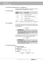
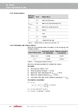
5.2.1 Nomenclature
Brief des-
ignation
Unit
Explanation
𝐴
𝑐𝑚
2
Piston surface area
𝐹
𝑎𝑥 𝑚𝑎𝑥
𝑘𝑁
Maximum axial actuating force
𝑝
𝑚𝑎𝑥
𝑏𝑎𝑟
Maximum supply pressure
𝐻
𝑚𝑚
Stroke
𝑡
𝑠
Time
𝑉
𝑐𝑚
3
Volume
𝜗
𝑙
𝑚𝑖𝑛
Volumetric flow rate
Table 5:
Nomenclature for selection of hydraulic unit
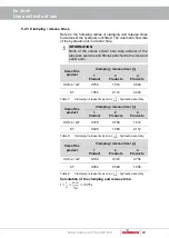
5.2.2 Clamping and release volume
Refer to the following table for details of the clamping and
release volume.
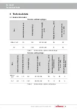
Size of the product
Clamping volume
𝑽
/ 1 product [
𝒍
]
Release volume
𝑽
/
1 product [
𝒍
]
XXS-4 / A-F
0.0252
0.0231
5-7
0.0352
0.0319
Table 6:
Clamping and release volumes
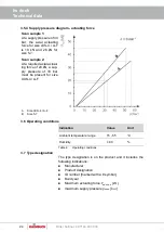
Here is a sample calculation to explain the values.
Example:
Hs dock size XXS-4 / A-F
Stroke [release stroke]
𝐻 = 4.0𝑚𝑚
Maximum axial actuating force
𝐹
𝑎𝑥 𝑚𝑎𝑥
= 35𝑘𝑁
Maximum supply pressure
𝑝
𝑚𝑎𝑥
= 56𝑏𝑎𝑟
Volumetric flow rate of the hydraulic assembly
𝜗 = 4
𝑙
𝑚𝑖𝑛
Volumetric calculation:
𝑉 = 𝐴 ∗ 𝐻
𝑝 =
𝐹
𝐴
→
𝐴 =
𝐹
𝑝
=
35000𝑁
56∗10
𝑁
𝑐𝑚2
= 62.5𝑐𝑚
2
𝑉 = 𝐴 ∗ 𝐻 = 62.5𝑐𝑚
2
∗ 0.4𝑐𝑚
𝑉 = 25𝑐𝑚
3
= 0.025𝑑𝑚
3
= 0.025𝑙


