background image

9

HAIKU® BY BIG ASS FANS

STEP COMPLETED

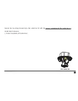
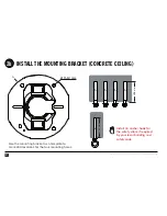
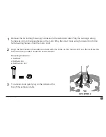
Using the mounting bracket (

a

) as a template, mark drill locations for the four mounting holes on the 

concrete ceiling. Drill four Ø 11–12 mm holes into the marks. The hole depth should be at least 50 
mm.

Remove any dust from the holes. Insert four anchor bolts (

b

) into the holes. Strike the heads of the 

anchor bolts with a hammer, ensuring the bolt sleeves are flush with the ceiling surface.

Concrete Ceiling Hardware:
b. (4) Ø 6 mm anchor bolts (not supplied)

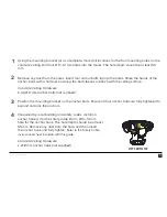
Position the mounting bracket on the anchor bolts. Ensure all four anchor bolts are fully tightened to 
expand and lock the anchors.

If required by local building and safety codes, install an 
anchor hook (

c

) for the safety cable. Drill a Ø 13–14 mm 

hole for the anchor hook. The hole depth should be at least 
65 mm. Remove any dust from the hole, and then insert 
the anchor hook and fully tighten. 

Refer to the Safety Cable 

instructional sheet included with this guide.

Concrete Ceiling Hardware:
c. Ø


8 mm anchor hook (not supplied)

3

2

1

4

Содержание FR127C-U1EXX

Страница 1: ...INSTALLATION GUIDE INSTALLATION GUIDE ...

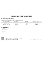
Страница 2: ...ltage Operating voltage Diameter Weight Operating frequency 120 VAC 1 Φ 132 cm 5 kg 60 Hz 220 240 VAC 1 Φ 132 cm 5 kg 50 60 Hz Tools Needed Ladder Wire Strippers Phillips Screwdriver Hex Key Wrenches Models L3127 X5 L3127 X6 FR127C U1EXX Scan or visit resources haikuhome com help for online Haiku mobile app help ...

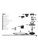
Страница 3: ...g Bracket Control Box Wiring Cover LED Diffuser Ring Mounting Ball and Hardware Lower Cover Trim Lower Cover Ring Extension Tube Motor Unit 3 Airfoils Remote Control Hardware Pack PARTS a b c d e f g h i j k l a b c d e f g h i j k l ...

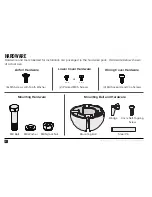
Страница 4: ...rdware pack Hardware below shown at actual size Mounting Hardware M8 Bolt M8 Washer M8 Nylock Nut Airfoil Hardware 6 M5 Screws with Tooth Washer Lower Cover Hardware Mounting Ball and Hardware Steel Pin Wedge 4 mm Self Tapping Screw Mounting Ball 2 Painted M3 5 Screws or Black White Wiring Cover Hardware 4 M4 Socket Head Cap Screws ...

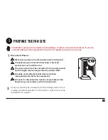
Страница 5: ... electrical code a licensed electrician must install the fan The ground wire must be connected to the supply ground and its length must be longer than the safety cable A readily accessible disconnect device shall be incorporated external to the equipment A means for disconnection must be incorporated in the fixed wiring in accordance with the wiring rules If you are installing the fan directly to ...

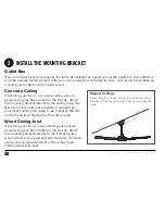
Страница 6: ... Attach the mounting bracket directly to the ceiling using four Ø 6 mm anchor bolts not supplied If required by your local building and safety code install an Ø 8 mm anchor hook not supplied for the safety cable Wood Ceiling Joist If installing your fan on a wood ceiling joist ensure power wiring has been routed to the fan site Attach the mounting bracket directly to the joist using two wood screw...

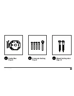
Страница 7: ...5 HAIKU BY BIG ASS FANS 2a Outlet Box Page 6 2c Wood Ceiling Joist Page 10 2b Concrete Ceiling Page 8 ...

Страница 8: ...6 REV F 06 08 2018 2015 BIG ASS FANS ALL RIGHTS RESERVED INSTALL THE MOUNTING BRACKET OUTLET BOX 2a b a c Installation may vary Refer to the outlet box instructions ...

Страница 9: ...7 HAIKU BY BIG ASS FANS STEP COMPLETED Secure the mounting bracket a to the outlet box b with the screws supplied with the outlet box c Outlet Box Hardware c Screw supplied with outlet box ...

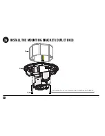
Страница 10: ...RESERVED INSTALL THE MOUNTING BRACKET CONCRETE CEILING 2b c 65 mm a Ø 11 12 mm Use the mounting bracket as a template to mark drill locations for the four mounting holes Install an anchor hook for the safety cable if required by your local building and safety code ...

Страница 11: ...e ceiling surface Concrete Ceiling Hardware b 4 Ø 6 mm anchor bolts not supplied Position the mounting bracket on the anchor bolts Ensure all four anchor bolts are fully tightened to expand and lock the anchors If required by local building and safety codes install an anchor hook c for the safety cable Drill a Ø 13 14 mm hole for the anchor hook The hole depth should be at least 65 mm Remove any d...

Страница 12: ...10 REV F 06 08 2018 2015 BIG ASS FANS ALL RIGHTS RESERVED INSTALL THE MOUNTING BRACKET WOOD CEILING JOIST 2c a b not supplied ceiling joist ...

Страница 13: ...ASS FANS Secure the mounting bracket a to the joist with two 2 12 11 x 45 mm hex head timber screws with seal b Wood Ceiling Joist Hardware b 2 12 11 x 45 mm hex head timber screws with seal not supplied STEP COMPLETED ...

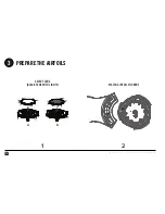
Страница 14: ...12 REV F 06 08 2018 2015 BIG ASS FANS ALL RIGHTS RESERVED PREPARE THE AIRFOILS 3 1 2 a b SELECT LENS BLACK FANS WITH LIGHTS MATCH AIRFOIL STICKERS ...

Страница 15: ...lights For softer lighting remove the white lens and install the smoky lens before attaching the airfoils a Twist to uninstall white lens b Twist smoky lens to lock in place Make sure the stickers on the airfoils match the stickers on the fan hub ...

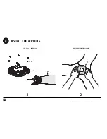
Страница 16: ...14 REV F 06 08 2018 2015 BIG ASS FANS ALL RIGHTS RESERVED INSTALL THE AIRFOILS 4 b c a 1 2 d INSTALL AIRFOILS FANS WITHOUT LIGHTS ...

Страница 17: ...er tools to install the airfoils and do not over tighten the screws Over tightening the screws may cause the airfoils to warp and void your warranty Airfoil Hardware c 6 M5 screws with tooth washer Fans without lights Position the motor cover d over the motor and then place both hands flat on the cover and turn it clockwise to lock it in place STEP COMPLETED DO NOT USE POWER TOOLS 2 1 ...

Страница 18: ...16 REV F 06 08 2018 2015 BIG ASS FANS ALL RIGHTS RESERVED INSTALL THE LOWER EARTH GROUND WIRE 5 a c 1 2 b d SECURE EARTH GROUND WIRE POSITION EXTENSION TUBE ...

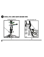
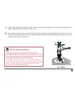
Страница 19: ... the yellow Earth Ground female spade connector c to the male connector d on the motor Safety Cable Installation You may be required to secure the fan directly to the building structure if your local safety code requires it Check your local code Refer to the Safety Cable instructional sheet included with this guide for more information Acceptable building structures include a wooden beam or a meta...

Страница 20: ...18 REV F 06 08 2018 2015 BIG ASS FANS ALL RIGHTS RESERVED 6 CONNECT MOTOR WIRING AND SECURE EXTENSION TUBE 1 3 2 c d e SECURE HARDWARE REMOVE SLACK INSTALL WIRING HARNESSES a a b ...

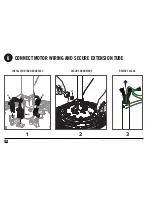
Страница 21: ... small male wiring harness b into the female wiring harness from the motor shaft Align the bolt holes on the extension tube with the holes on the motor shaft and then secure the tube with the provided hardware and wrenches Mounting Hardware c M8 bolt d M8 washer e M8 nylock nut To remove slack gently tug on the cables at the top of the extension tube STEP COMPLETED 2 1 3 ...

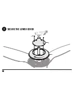
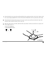
Страница 22: ...20 REV F 06 08 2018 2015 BIG ASS FANS ALL RIGHTS RESERVED SECURE THE LOWER COVER c 7 b a ...

Страница 23: ...rfoils Rotate the cover ring clockwise until it stops Thread the wires through the opening in the lower cover trim b and then slide the trim down the extension tube resting it evenly on the cover ring Align the screw holes on the trim with the motor screw holes and then secure the trim in place with the provided screws c Lower Cover Hardware c 2 Painted M3 5 screws or Black White 2 1 3 ...

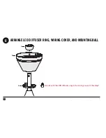
Страница 24: ...22 REV F 06 08 2018 2015 BIG ASS FANS ALL RIGHTS RESERVED ARRANGE LED DIFFUSER RING WIRING COVER AND MOUNTING BALL 8 a b c Do not seat the LED diffuser ring in the wiring cover at this step ...

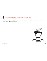
Страница 25: ...S FANS STEP COMPLETED Slide the LED diffuser ring a wiring cover b and mounting ball c down the extension tube in that order resting them on the fan hub Do not seat the LED diffuser ring in the wiring cover at this step ...

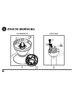
Страница 26: ...24 REV F 06 08 2018 2015 BIG ASS FANS ALL RIGHTS RESERVED ATTACH THE MOUNTING BALL 9 c a b Inner slot SEAT MOUNTING BALL 2 1 INSTALL WEDGE ...

Страница 27: ...n in the inner slots of the ball Mounting Ball Hardware a Steel pin Insert the wedge b into the mounting ball as shown and then secure the wedge with the screw c Tighten the screw enough to prevent movement between the mounting ball and extension tube Do not over tighten the screw Mounting Ball Hardware b Wedge c 4 mm self tapping screw STEP COMPLETED 2 1 ...

Страница 28: ...26 REV F 06 08 2018 2015 BIG ASS FANS ALL RIGHTS RESERVED HANG THE FAN 10 Slot Rib ...

Страница 29: ... Align the slot in the mounting ball with the rib in the mounting bracket insert the mounting ball and let the fan hang freely Gently twist the extension tube to ensure the mounting ball is properly seated and will not move during fan operation STEP COMPLETED 2 1 ...

Страница 30: ...28 REV F 06 08 2018 2015 BIG ASS FANS ALL RIGHTS RESERVED INSTALL THE UPPER EARTH GROUND WIRE 11 b c a ...

Страница 31: ...u may be required to secure the fan directly to the building structure if your local safety code requires it Check your local code Refer to the Safety Cable instructional sheet included with this guide for more information Acceptable building structures include a wooden beam or a metal mounting brace secured between two beams In some cases it may be necessary to install additional structural mater...

Страница 32: ...30 REV F 06 08 2018 2015 BIG ASS FANS ALL RIGHTS RESERVED 12 WIRE THE FAN GREEN BLUE BROWN a A C H O T L 1 A C N E U T R A L L 2 P E E A R T H G R O U N D ...

Страница 33: ...trical installation of this fan Make the electrical connections by securing the supply power wires to the loose ends of the wiring harness a with the provided wire nuts or a terminal strip or the means of connection required by your local electrical code Test the connection by lightly tugging on the wires Tuck the power wiring into the outlet box or building structure AC HOT L1 BROWN AC NEUTRAL L2...

Страница 34: ...32 REV F 06 08 2018 2015 BIG ASS FANS ALL RIGHTS RESERVED INSTALL THE CONTROL BOX 13 a 1 2 b ...

Страница 35: ...rol box a into the mounting bracket as illustrated Be careful not to pinch the wires between the mounting bracket and control box Snap the LED indicator b into the gap in the mounting bracket Make sure it is securely seated STEP COMPLETED 2 1 ...

Страница 36: ...34 REV F 06 08 2018 2015 BIG ASS FANS ALL RIGHTS RESERVED CONNECT THE CONTROL BOX 14 e d a 1 2 b c ...

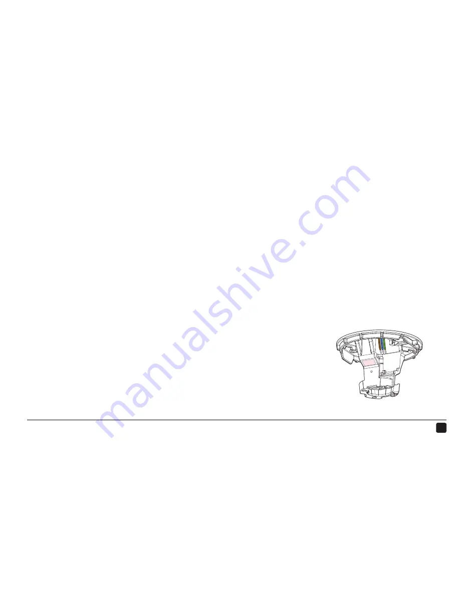
Страница 37: ... a to the harness from the ceiling b Peel the backing off the double sided tape c on the mounting bracket and then affix the harnesses to the tape Connect the wiring harnesses from the extension tube d to the corresponding receptacles e on the control box STEP COMPLETED 1 2 ...

Страница 38: ...36 REV F 06 08 2018 2015 BIG ASS FANS ALL RIGHTS RESERVED INSTALL THE WIRING COVER 15 1 2 a c d View from below b b ALIGN WIRING COVER INSTALL SCREWS INSTALL DIFFUSER RING 3 b ceiling ceiling ceiling ...

Страница 39: ...ugh the opening in the cover b Make sure all wiring is tucked into the wiring cover and then secure the cover with the provided screws c Wiring Cover Hardware c 4 M4 socket head cap screws Slide the LED diffuser ring d up the extension tube and plug the connector into the LED indicator receptacle through the opening b in the wiring cover Make sure the tabs on the diffuser ring are securely snapped...

Страница 40: ...eed and light brightness Applies only to fans with lights Turns fan on or off Sets fan timer length of up to eight hours Each press extends timer by one hour Turns light on or off Clears active fan timer Increases fan speed light brightness Varies fan speed to simulate a natural breeze Decreases fan speed light brightness Automatically adjusts your fan speed overnight to keep you comfortable while...

Страница 41: ...8 Australia Oceania Unit 22 1029 Manly Road Tingalpa QLD 4173 Australia 1 300 BIG ASS Europe OBELIS S A Bd Général Wahis 53 1030 Brussels Belgium 32 2 732 59 54 Asia Pacific 18 Tampines Industrial Crescent 06 07 Singapore 528 605 65 6709 8500 East Asia Room 808 Tai Yau Building 181 Johnston Road Wan Chai Hong Kong 852 2836 5808 ...

Страница 42: ...NOTES ...

Страница 43: ...his document is subject to change without notice May be protected by one or more patents listed at www bigassfans com patents Haiku is a trademark of Delta T LLC registered in the U S and or other countries For warranty information visit haikuhome com ...

Страница 44: ...HKU INST 74 ENG 01 LP ...

Отзывы: