background image

Operating & Maintenance Manual 


www.haigh.co.uk 

900-029082-4 – Dec 16 

22 

Storage (Customer) 

If the machine is not to be installed immediately, it should be stored in the carton in which it has 

been transported, in a clean, dry place which is free from vibration. 
Undo the carton, lift the lid to periodically rotate the impeller by hand to prevent the mechanical seal 

seizing. Re-seal the carton after doing this. 

Industrial gloves must be worn when working on or rotating the impeller by hand. 

Removing From Storage (Customer) 

If the machine has been stored, ensure that the impeller boss is free to rotate. The mechanical seal 

may have seized if it has not been revolved frequently or through water drying out. Result: Motor will 

not start, or does start and damages seal faces. 
To free the mechanical seal: 

  Remove the impeller and part the seal faces, lubricate with clean water only. 

  A new mechanical seal will be required if faces are damaged as the seal will leak. 

Note: 


Industrial gloves must be worn when working on or rotating the impeller by hand. 

  Never put tools etc. on the cabinet top, these could damage the surface. 

  Never allow the pump to run in a dry condition. 

Unpacking the Machine 

1.  Remove the carton and any packing materials. 

2.  Remove the front panel screw, hold both sides of the front panel at the bottom and pull to 

release it and access the interior. 

3.  Remove the electrical control box to access the central fixing down bolt. 

4.  Remove the central fixing down bolt. 

5.  Remove the machine from the pallet. 

6.  Remove the bolts that secure the floor locating bracket to the pallet. The floor locating bracket 

will be used to fix the machine to the floor and is positioned by using the template (supplied). 

7.  The machine is now ready for installation. 


Содержание Quattro

Страница 1: ......

Страница 2: ...ded warranty or Service Contract is available by contacting our sales office Damage caused by misuse is chargeable and will invalidate the warranty as will poor installation if the machine is not inst...

Страница 3: ...Operating Maintenance Manual www haigh co uk 900 029082 4 Dec 16...

Страница 4: ...Operating Maintenance Manual www haigh co uk 900 029082 4 Dec 16...

Страница 5: ...k 900 029082 4 Dec 16 Table of Contents 1 Safety Precautions Procedures 2 Equipment Description Process and Control 3 Installation Commissioning 4 Maintenance Servicing Procedures 5 Part Identificatio...

Страница 6: ...www haigh co uk 900 029082 4 Dec 16...

Страница 7: ...Operating Maintenance Manual www haigh co uk 900 029082 4 Dec 16 1 1 Safety Precautions Procedures...

Страница 8: ...Operating Maintenance Manual www haigh co uk 900 029082 4 Dec 16 2...

Страница 9: ...these general safety instructions you must observe the special safety instructions which are included in other sections of this manual Safety Symbols and Instructions The Hazard Sign This sign is use...

Страница 10: ...or install the machine must be suitably trained and qualified and have the necessary equipment or tools to carry out their tasks safely The person who is responsible for staff supervision should defin...

Страница 11: ...taminated All safety devices Interlocks must be refitted and be in working order immediately after the work is carried out and their operations checked Arbitrary Modifications Replacement of Product P...

Страница 12: ...Operating Maintenance Manual www haigh co uk 900 029082 4 Dec 16 6...

Страница 13: ...Operating Maintenance Manual www haigh co uk 900 029082 4 Dec 16 7 2 Equipment Description Process and Control...

Страница 14: ...Operating Maintenance Manual www haigh co uk 900 029082 4 Dec 16 8...

Страница 15: ...tored by the internal microprocessor If a problem occurs cycle termination devices end the cycle of operation and the respective warning or fault light will illuminate For operation refer to the indic...

Страница 16: ...Operating Maintenance Manual www haigh co uk 900 029082 4 Dec 16 10 Installation Diagram...

Страница 17: ...cle 2 18 5ltrs Cycle 3 23ltrs Cistern Overflow Indicator Never connect the overflow indicator stub to the drain Ensure any discharge is Visible Direction Of Rotation For Macerator Motor Single phase m...

Страница 18: ...g of attention required Indicator light Red Machine indicating fault Call for service engineer Please Quote Fault Code when calling See Page 50 Water Filling Rising until the tank is full Illuminated...

Страница 19: ...ad for this machine Disposable bedpans Four Urine bottles Four Any combination of products above Four Wash bowls Two DO NOT exceeded this maximum loading 3 Close the lid the lid will lock and the mach...

Страница 20: ...of the machine jamming do not place the bedpans inside each other when putting them in the hopper If electrical power to the machine fails during an operation cycle the interlock remains engaged The...

Страница 21: ...Operating Maintenance Manual www haigh co uk 900 029082 4 Dec 16 15 Replace Haigh Internal MaciFreshTM Kit 1 2 3 4 5 6 7 8...

Страница 22: ...Operating Maintenance Manual www haigh co uk 900 029082 4 Dec 16 16...

Страница 23: ...Operating Maintenance Manual www haigh co uk 900 029082 4 Dec 16 17 3 Installation Commissioning...

Страница 24: ...Operating Maintenance Manual www haigh co uk 900 029082 4 Dec 16 18...

Страница 25: ...e flow rate the initial fill of the machine is timed Initial Fill Time Flow Rate 87 seconds 9 lpm 142 seconds 5 5 lpm The flow regulator may not be removed to improve the flow as this will invalidate...

Страница 26: ...a 50mm pipe stub The outlet is for rear connection Fitting a slow bend will allow for alternative connections through the floor to the right and to the left Never connect waste outlet to a septic tan...

Страница 27: ...customer s isolator Mains supplies always to be protected by I E C approved circuit breakers or fuses The thermal relay overload device in the motor circuit should always be set for a value correspond...

Страница 28: ...e the mechanical seal Remove the impeller and part the seal faces lubricate with clean water only A new mechanical seal will be required if faces are damaged as the seal will leak Note Industrial glov...

Страница 29: ...chine forward on the runners underneath until the floor locating bracket locates in the two guide slots in the runners 6 Secure the machine and connect services Replace the mounting base bolt under th...

Страница 30: ...e drain is connected Electrical checks Check that the electrical connection is made in accordance with the previous section Impeller direction of rotation three phase machines only The rotational dire...

Страница 31: ...Operating Maintenance Manual www haigh co uk 900 029082 4 Dec 16 25 4 Maintenance Servicing Procedures...

Страница 32: ...Operating Maintenance Manual www haigh co uk 900 029082 4 Dec 16 26...

Страница 33: ...lock pressure switch tube is clear of water Check and clean solenoid filter or replace Mechanical Check wear on the hopper cutter ring impeller Check that the impeller is rotating freely and for absen...

Страница 34: ...signed for minimum maintenance The clip bushes used in this machine must not be lubricated Apply anti seize compound if indicated The motor is fitted with sealed for life bearings The mechanical seal...

Страница 35: ...Operating Maintenance Manual www haigh co uk 900 029082 4 Dec 16 29 5 Part Identification Diagrams...

Страница 36: ...Operating Maintenance Manual www haigh co uk 900 029082 4 Dec 16 30...

Страница 37: ...Quattro Ensure appropriate protective equipment is worn ALWAYS isolate the machine from mains electrical supply before servicing Isolate the water inlet to the pump at the service valve by turning th...

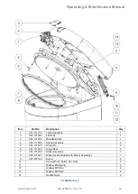
Страница 38: ...Operating Maintenance Manual www haigh co uk 900 029082 4 Dec 16 32 General Assembly...

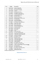
Страница 39: ...kit 1 19 901 111567 Pulveriser Head Assembly 1 20 901 110919 Hopper Head Seal 1 21 901 110942 Drain Outlet Assy 1 22 901 111848 Pump Assy 1 901 100226 Pump 23 705 006218 Washer 5mm Plain 2 24 90X 1125...

Страница 40: ...901 111409 Release Button 1 4 902 111488 Spring Assembly 2 5 901 111522 Hinge Pin 2 6 901 111523 Hinge Boss 2 7 901 111600 Striker Assembly 1 8 901 111421 Striker Seal included with Striker Assembly 1...

Страница 41: ...y 1 2 901 111596 Lid Support c w Hinge Brackets and Spring Assemblies 1 3 900 013486 Spray Vent 1 4 901 111288 Spray Inlet 1 5 901 111593 PCB 1 6 901 111571 LCD 1 7 905 003571 Pressure Switch 1 8 900...

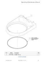
Страница 42: ...Operating Maintenance Manual www haigh co uk 900 029082 4 Dec 16 36 Item Part No Description Qty 1 902 110877 Cabinet Top 1 2 901 111006 Hopper Top Seal 1 Cabinet Top Assembly...

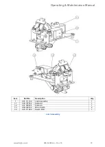
Страница 43: ...al www haigh co uk 900 029082 4 Dec 16 37 Item Part No Description Qty 1 901 111199 Latch Assembly 1 1 1 902 107552 Solenoid 1 1 2 901 030234 Solenoid 1 1 3 900 030183 Micro Switch 2 1 4 901 111880 Sw...

Страница 44: ...Operating Maintenance Manual www haigh co uk 900 029082 4 Dec 16 38 Main Pump Deodoriser Pump Removal Diagram...

Страница 45: ...Operating Maintenance Manual www haigh co uk 900 029082 4 Dec 16 39 Mechanical Assembly Removal...

Страница 46: ...Operating Maintenance Manual www haigh co uk 900 029082 4 Dec 16 40...

Страница 47: ...Mechanical Seal 1 5 901 111573 Seal Housing 1 6 901 111266 Motor Hinge Plate Assy 1 7 955 051206 O Ring 1 8 901 013921 Impeller Hub 1 9 901 013841 Lock Washer 1 10 901 111568 Sealed Screw Assy 4 11 90...

Страница 48: ...Operating Maintenance Manual www haigh co uk 900 029082 4 Dec 16 42 Plumbing Diagram...

Страница 49: ...ssembly BLUE Identifier 1 11 901 103002 10mm Tube To 8mm Hose Stem JG PM251008E 1 12 901 101313 Tee 10 X 10 X 10 JG PM0210E 1 13 907 111546 Hose Stub 1 14 900 013608 Stem Elbow 12 X 12 JG PM022121E 1...

Страница 50: ...2 030154 A7 Overload Device 4 0 6 2A 1 904 030154 Overload Device 1 2 1 9A 1 4 106 031088 A5 Relay 1 1 5 129 031012 End Stop 1 6 100 031012 Grey Terminal 1 1 7 125 031012 Fused Terminal 1 3 8 111 0310...

Страница 51: ...Operating Maintenance Manual www haigh co uk 900 029082 4 Dec 16 45 Wiring Diagram Single Phase...

Страница 52: ...Operating Maintenance Manual www haigh co uk 900 029082 4 Dec 16 46 Wiring Diagram 3 Phase...

Страница 53: ...enoid latching Lid Lock B5 902 107552 Solenoid Lid Release B6 901 111812 Pump Deodoriser C1 900 030183 Micro switch Safety monitoring C2 900 030183 Micro switch Safety monitoring C3 900 003940 Positiv...

Страница 54: ...e Opening Kit Part No Description 905 112632 Foot Pedal Hands Free Opening Kit 906 112632 Foot Pedal Hands Free Opening Kit Plinth Compatible On early models the Additional Pressure Switch was fitted...

Страница 55: ...Operating Maintenance Manual www haigh co uk 900 029082 4 Dec 16 49 6 Fault Finding Troubleshooting...

Страница 56: ...Operating Maintenance Manual www haigh co uk 900 029082 4 Dec 16 50...

Страница 57: ...he jet gap must be the same around its circumference If the problem is with the pump you will require an exchange unit for this part Lid seal is leaking Check that the lid seal sits centrally on the l...

Страница 58: ...t malfunction Interlock micro switch circuit broken during machine operation Remove lid cover Check micro switch MS 1 and MS 2 operation Check MS 1 and MS 2 circuits for continuity F3 Contactor circui...

Страница 59: ...fter 150 seconds Lack of water in cistern Check that the mains inlet valve is open Check that there is sufficient water pressure Check and clean the inlet solenoid filter Check solenoid valve is opera...

Страница 60: ...Operating Maintenance Manual www haigh co uk 900 029082 4 Dec 16 54...

Отзывы: