Commercial Air Conditioner
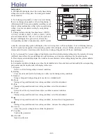
00: 1~64 01: 65~128
10: 129~192 11: 193~256
position
1
0: ON
1: OFF
indoor bus line
central bus line
2
master controller
slave controller
3
4
For example:
Select central bus line, master central controller, control range is 00, so the dip switch is 1 0 0 0 (default)
Select indoor bus line, master central controller, control range is 00, so the dip switch is 0 0 0 0.
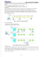
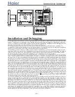
1.9.7. Can set the central control unit as a group, and the max. 64 units of indoor can be set a group.
After setting unit, the indoor in one group can be controlled the same operation (when out of factory, one
unit is regarded as one group).
central controller
connecting board
IGU04
Indoor 1
Indoor 2
Indoor 3
Indoor 1
Indoor 2
Indoor 3
Figure 5 Central unit and group diagram
YR-E12
YR-E12
YR-E12
Unit 1
Unit 2
Unit 3
1.9.8. Control function
1. Features and functions of central controller
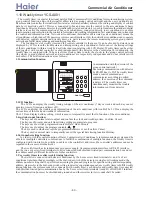
Central controller control(ICR01) diagram is as below:
Figure 6 MRV II central control system diagram
connecting board ...
IGU04
outdoor
central controller
ICR01
connecting board5
IGU04
connecting board 1
IGU04
outdoor
outdoor
unit 1
unit 2
wired controller
wired controller
wired controller
max. 16 indoors
unit 64 (max. 64 units)
unit 3
Infrared controller
YR-E12
YR-E12
YR-H71
YR-H71
B-A
B-B
P,Q
P,Q
P,Q
1.9.9.Summarization
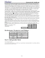
For installation, connect communication wires from central controller ICR01 port B-A,B-A, to connecting board IGU04. and then connect
communication wires from IGU04 P,Q to outdoor or indoor unit communication port P,Q. Notice, the default position of ICR01 dip switch
is 1 0 0 0, the address of IGU04 and the indoor address must be set in different number.
When one central controller control one air condition system, also can directly connect wires from ICR01 B-A,B-B port to P, Q port of
outdoor or indoor communication port.
z
37
z
Содержание YR-H71
Страница 10: ...10 once...


