


17
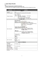
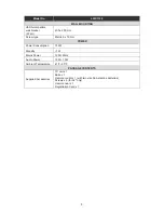
3. Input/Output Specification
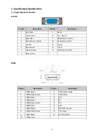
3.1 Input Signal Connector
D-SUB
Pin No.
Description
Pin No.
Description
1
Red Video
9
No Pin
2
Green Video
10
Sync Ground
3
Blue Video
11
SDA(Remote Control)
4
SCL(Remote Control)
12
Serial Data for DDC
5
Ground
13
H-Sync
6
Red Ground
14
V-Sync
7
Green Ground
15
Serial Clock for DDC
8
Blue Ground
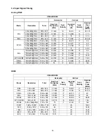
HDMI
Pin No.
Description
Pin No.
Description
1
TMDS Data2+
11
TMDS Clock Shield
2
TMDS Data2 Shield
12
TMDS Clock-
3 TDMS
Data2-
13 CEC
4 TMDS
Data1+
14 NC
5 TMDS
Data1
Shield
15 SCL
6 TMDS
Data1-
16 SDA
7
TMDS Data0+
17
DDC/CEC Ground
8
TMDS Data0 Shield
18
+5V Power
9
TMDS Data0-
19
Hot Plug Detect
10 TMDS
Clock+
Содержание L32C1120
Страница 7: ...7 2 2 To Use the Menus ...
Страница 8: ...8 ...
Страница 9: ...9 ...
Страница 10: ...10 ...
Страница 11: ...11 ...
Страница 12: ...12 ...
Страница 13: ...13 ...
Страница 14: ...14 ...
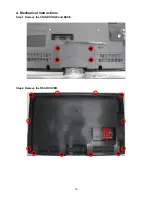
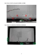
Страница 19: ...19 4 Mechanical Instructions Step1 Remove the STAND HINGE and BASE Step2 Remove the REAR COVER ...
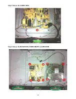
Страница 20: ...20 Step3 Remove the POWER CORD Step4 Remove the MAIN BOARD POWER BOARD and SPEAKERS ...
Страница 21: ...21 Step5 Remove the BKT and separate the BEZEL and PANEL Step6 Remove the IR BOARD KEY BOARD and LED BOARD ...
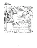
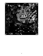
Страница 29: ...29 6 PCB Layout 6 1 Main Board 715G3269M01001005K ...
Страница 30: ...30 ...
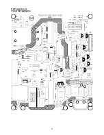
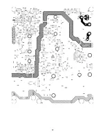
Страница 31: ...31 6 2 Power Board 715G3770P02W20003S ...
Страница 32: ...32 ...
Страница 33: ...33 ...
Страница 34: ...34 6 3 LED Board 715G4252T02000004S 6 4 Key Board 715G4234K02000004S ...
Страница 35: ...35 6 5 IR Board 715G4247R02000004S ...