background image

Page  17

31-5000752   Rev. 0

A - 

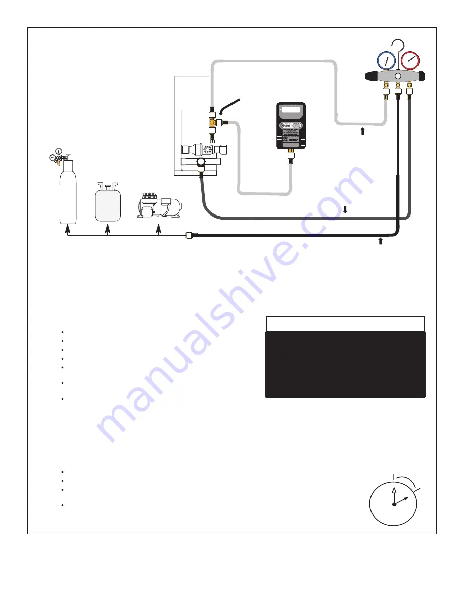
Open both manifold valves and start the vacuum pump.

B - 

NOTE - During the early stages of evacuation, it is desirable to close the manifold gauge valve at least once. A rapid rise in pressure

indicates a relatively large leak. If this occurs, 

repeat the leak testing procedure.

NOTE - The term absolute pressure means the total actual pressure above absolute zero within a given volume or system. Absolute

pressure in a vacuum is equal to atmospheric pressure minus vacuum pressure.

C - 

When  the  absolute  pressure  reaches  23,000  microns (29.01 inches of

mercury), perform the following:

Close manifold gauge valves.
Close valve on vacuum pump.
Turn off vacuum pump.
Disconnect manifold gauge center port hose from vacuum pump.
Attach  manifold  center  port  hose  to  a  nitrogen  cylinder  with  pressure

regulator set to 150 psig (1034 kPa) and purge the hose.
Open manifold gauge valves to break the vacuum in the line set and indoor

unit.
Close manifold gauge valves.

D - 

Shut off the nitrogen cylinder and remove the manifold gauge hose from the cylinder. Open the manifold gauge valves to release the

nitrogen from the line set and indoor unit.

E - 

Reconnect the manifold gauge to the vacuum pump, turn the pump on, and continue to evacuate the line set and indoor unit until the

absolute pressure does not rise above 500 microns (29.9 inches of mercury) within a 20-minute period after shutting off the vacuum pump

and closing the manifold gauge valves.

F - 

When the absolute pressure requirement above has been met, disconnect the manifold hose from the vacuum pump and connect it to a

cylinder of HFC-410A positioned to deliver liquid refrigerant. Open the manifold gauge valve 1 to 2 psig in order to release the vacuum in the

line set and indoor unit.

G - 

Perform the following:

Close manifold gauge valves.
Shut off HFC-410A cylinder.
Reinstall service valve cores by removing manifold hose from service valve. Quickly install cores with core

tool while maintaining a positive system pressure.
Replace stem caps and finger tighten them, then tighten an additional one-sixth (1/6) of a turn as illustrated.

OUTDOOR

UNIT

TO VAPOR

SERVICE VALVE

TO LIQUID LINE

SERVICE VALVE

MICRON

GAUGE

VACUUM PUMP

1/4 SAE TEE WITH SWIVEL

COUPLER

500

MANIFOLD

GAUGE SET

HFC-410A

RECOMMEND

MINIMUM 3/8” HOSE

A - 

Connect low side of manifold gauge set with

1/4 SAE in-line tee to 

vapor 

line service valve

B - 

Connect high side of manifold gauge set to

liquid 

line service valve

C - 

Connect available micron gauge connector

on the 1/4 SAE in-line tee.

D - 

Connect the  vacuum pump (with vacuum

gauge)  to  the  center  port  of  the  manifold

gauge set. The center port line will be used

later for both the HFC-410A and nitrogen

containers.

HIGH

LOW

1

2

3

4

5

6

7

8

9

10

11 12

1/6 TURN

NITROGEN

3

CONNECT GAUGE SET

A

B

C

D

4

EVACUATE THE SYSTEM

NOTE - Remove cores from service valves (if not already done).

Possible equipment damage.
Avoid deep vacuum operation. Do not use

compressors  to  evacuate  a  system.

Extremely low vacuum can cause internal

arcing  and  compressor  failure.  Damage

caused  by  deep  vacuum  operation  will

void warranty.

WARNING !

EVACUATION

H - 

Open suction service valve first before liquid valve to release the unit charge into the system. Replace valve

caps and tighten (8 ft. lb.). Caps are the primary seal.

Evacuate the line set and indoor unit until a slight vacuum is indicated on the micron gauge (approximately 23,000 microns or 

29.01 inches of mercury).

NOTE - Position 

canister to deliver 

liquid refrigerant.

Содержание GE APPLIANCES NS17HS

Страница 1: ...31 5000752 Rev 0 11 22 GEA READ CAREFULLY KEEP THESE INSTRUCTIONS NS17HS SINGLE STAGE HIGH EFFICIENCY SPLIT SYSTEM HEAT PUMP UP TO 17 SEER 9 5 HSPF UP TO 16 SEER2 8 5 HSPF2 Service Manual...

Страница 2: ...al for personal injury or death Electric shock hazard Can cause injury or death Before attempting to perform any service or maintenance turn the electrical power to unit OFF at disconnect switch es Un...

Страница 3: ...53 33 9 50 25 0 120 0 2 6 1 3 825 NS17H60SA4 208 230 60 1 197 253 32 5 50 23 9 124 5 2 6 1 3 825 UNIT DIMENSIONS IN Model Dimensions inch Shipping Weight lbs A Width B Depth C Height NS17H18SA4 28 25...

Страница 4: ...146 H4TXV02 7 8 3 8 7 8 3 8 7 8 3 8 NS17H60SA4 164 H4TXV03 1 1 8 3 8 1 1 8 3 8 7 8 3 8 Factory charged for 15 feet of line set adjust per installation instructions Field supplied adapter required COO...

Страница 5: ...ompressors usually do not require hard start maybe needed for utility brown out or low voltage areas 42 48 60 81J69 Crankcase Heater 18 24 30 93M04 Prevents liquid migration to compressor in cold weat...

Страница 6: ...e 6 31 5000752 Rev 0 FAN BLADE SPECS 4SHP17LE 51 Fan Blade Dia of Blades Pitch Part 18 22 2 24 23C06 24 22 2 24 23C06 30 22 2 24 23C06 36 26 3 24 23V42 42 26 3 29 23V43 48 26 3 29 23V43 60 26 3 29 23V...

Страница 7: ...Page 7 31 5000752 Rev 0 Figure 1 Typical Parts Arranegment Figure 2 Typical Parts Arranegment...

Страница 8: ...the outdoor section To reduce the possibility of noise transmission the foundation slab should NOT be in contact with or be an integral part of the building foundation See Figure 3 General Read this e...

Страница 9: ...rhang is 36 NOTE At least one side should be unobstructed by a wall or other barrier Table 2 Clearances 30 around Control Box 24 6 Figure 4 NOTE See Table 2 for specific minimum clearance guidelines D...

Страница 10: ...enced burnout it is recommended that the existing line set and indoor coil be replaced NOTE Refrigeration Piping Use only refrigerant grade copper tubes Split systems may be installed with up to 50 fe...

Страница 11: ...STRAP THE LIQUID LINE TO THE VAPOR LINE FLOOR JOIST OR ROOF RAFTER REFRIGERANT LINE SET INSTALLING HORIZONTAL RUNS NOTE Similar installation practices should be used if line set is to be installed on...

Страница 12: ...instructions Figure 5 1 Connect gauges and equipment as shown in Figure 5 2 Set the recovery machine for liquid recovery and start the recovery machine Open the gauge set valves to allow the recovery...

Страница 13: ...sing bulb insulation is required if mounted external to the coil casing sensing bulb installation for bulb positioning STUB END TEFLON RING LIQUID LINE ASSEMBLY WITH BRASS NUT DISTRIBUTOR ASSEMBLY 3 I...

Страница 14: ...side to liquid line service valve service port B Connect gauge set center port to bottle of nitrogen with regulator C Remove core from valve in vapor line service port to allow nitrogen to escape NITR...

Страница 15: ...INT FLAME AWAY FROM SERVICE VALVE PREPARATION FOR NEXT STEP 7 WRAP SERVICE VALVES To help protect service valve seals during brazing wrap water saturated cloths around service valve bodies and copper...

Страница 16: ...ve on the high side of the manifold gauge set in order to pressurize the line set and the indoor unit E After a few minutes open one of the service valve ports and verify that the refrigerant added to...

Страница 17: ...frigerant Open the manifold gauge valve 1 to 2 psig in order to release the vacuum in the line set and indoor unit G Perform the following Close manifold gauge valves Shut off HFC 410A cylinder Reinst...

Страница 18: ...er may result in property damage Size wiring and circuit breaker s per Product Specifications and unit rating plate WARNING ELECTROSTATIC DISCHARGE ESD Precautions and Procedures Electrostaticdischarg...

Страница 19: ...th nameplate rating Field wiring connections are tight and factory wiring has not been disturbed and are tight Indoor fan motor is on correct speed tap 2 Set thermostat selector switch to OFF and fan...

Страница 20: ...When the low pressure switch trips the control board will cycle off the compressor and the strike counter in the board will count one strike The low pressure switch is ignored under the following con...

Страница 21: ...de Heating and cooling operation will be allowed in this fault condition NOTE The coil temperature probe is designed with a spring clip to allow mounting to the outside coil tubing Coil sensor locatio...

Страница 22: ...the control board will initiate a defrost cycle Actuation When the reversing valve is de energized the Y1 circuit is energized and the coil temperature is below 35 F 2 C the board logs the compressor...

Страница 23: ...rform demand or time temperature defrost operation System will still heat or cool ON ON Fault Demand Defrost Control Failure Indicates that demand defrost control has internal component failure Cycle...

Страница 24: ...jumper is installed on the DELAY pins the compressor will be cycled off for 30 seconds going in and out of the defrost mode Units are shipped with jumper installed on DELAY pins NOTE The 30 second off...

Страница 25: ...nser coils Use a soft bristle brush with light pressure only DO NOT damage or bend condenser coil fins Damaged or bent fins may affect unit operation Figure 9 Removing Louvers Remove two screws at top...

Страница 26: ...conditions that may cause panels to be blown around and battered WARNING REMOVAL STEP 1 INSERT PANEL UNDER UNIT TOP CAP LIP AND LIFT SLIGHTLY TO CLEAR SIDE LIP OF PANEL FROM BASE STEP 2 PANEL INSTALLA...

Страница 27: ...available in various configurations from different manufacturers The information below is typical for most thermostats Ask your dealer for specific information regarding the model of thermostat instal...

Страница 28: ...T OPERATE CONTACT YOUR SERVICING DEALER Be sure to describe the problem and have the model and serial numbers of the equipment available If warranty replacement parts are required the warranty must be...

Страница 29: ...Page 29 31 5000752 Rev 0 Figure 11 Typical Factory Wiring 018 through 036 models...

Страница 30: ...Page 30 31 5000752 Rev 0 Figure 12 Typical Factory Wiring 042 through 060 models...

Страница 31: ...Page 31 31 5000752 Rev 0 Figure 13 Wiring Diagram 018 036 Models...

Страница 32: ...Page 32 31 5000752 Rev 0 Figure 14 Wiring Diagram 042 060 Models...

Страница 33: ...IENT TEMPERATURE IS BELOW 65 F CHARGE THE SYSTEM IN HEATING MODE 2 ALL HEAT PUMPS HAVE FACTORY INSTALLED OUTDOOR TXV 3 START THE SYSTEM IN HEATING AND RAISE THE THERMOSTAT SETTING TO MAXIMUM SETTING 4...

Страница 34: ...TEMPERATURE IS BELOW 65 F CHARGE THE SYSTEM IN HEATING MODE 2 ALL HEAT PUMPS HAVE FACTORY INSTALLED OUTDOOR TXV 3 START THE SYSTEM IN HEATING AND RAISE THE THERMOSTAT SETTING TO MAXIMUM SETTING 4 CHEC...

Страница 35: ...IENT TEMPERATURE IS BELOW 65 F CHARGE THE SYSTEM IN HEATING MODE 2 ALL HEAT PUMPS HAVE FACTORY INSTALLED OUTDOOR TXV 3 START THE SYSTEM IN HEATING AND RAISE THE THERMOSTAT SETTING TO MAXIMUM SETTING 4...

Страница 36: ...RATURE IS BELOW 65 F CHARGE THE SYSTEM IN HEATING MODE 2 ALL HEAT PUMPS HAVE FACTORY INSTALLED OUTDOOR TXV 3 START THE SYSTEM IN HEATING AND RAISE THE THERMOSTAT SETTING TO MAXIMUM SETTING 4 CHECK AIR...

Страница 37: ...AMBIENT TEMPERATURE IS BELOW 65 F CHARGE THE SYSTEM IN HEATING MODE 2 ALL HEAT PUMPS HAVE FACTORY INSTALLED OUTDOOR TXV 3 START THE SYSTEM IN HEATING AND RAISE THE THERMOSTAT SETTING TO MAXIMUM SETTIN...

Страница 38: ...OW 65 F CHARGE THE SYSTEM IN HEATING MODE 2 ALL HEAT PUMPS HAVE FACTORY INSTALLED OUTDOOR TXV 3 START THE SYSTEM IN HEATING AND RAISE THE THERMOSTAT SETTING TO MAXIMUM SETTING 4 CHECK AIR FLOW AND RUN...

Страница 39: ...E 1 IF AMBIENT TEMPERATURE IS BELOW 65 F CHARGE THE SYSTEM IN HEATING MODE 2 ALL HEAT PUMPS HAVE FACTORY INSTALLED OUTDOOR TXV 3 START THE SYSTEM IN HEATING AND RAISE THE THERMOSTAT SETTING TO MAXIMUM...

Страница 40: ...less than 15ft subtract this amount see Installation Instructions for more details Charge Using the Weigh in Method If the system is void of refrigerant locate and repair any leaks evacuate system and...

Страница 41: ...o charge shown on unit nameplate Indoor Matchup Subcool Additional Charge Heat 5 F Cool 1 F lbs oz 3 0 Ton HP NAM36P1 15 8 1 lb 2 oz NAM30P1 14 7 1 lb 6 oz NAM36E1 15 8 1 lb 2 oz NAM36V2 17 8 1 lb 1 o...

Страница 42: ...__________________________________________ Rated LoadAmpacity ________________ Compressor _______________________ Outdoor Fan ________________________ Maximum Fuse or Circuit Breaker _________________...

Страница 43: ...Page 43 31 5000752 Rev 0 Notes...

Страница 44: ...Printed in the U S A All specifications and illustrations subject to change without notice and without incurring obligations...

Отзывы: