


17
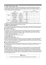
conditioning part load operation;
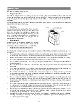
Energy-saving technical measures should be adopted as much as possible in the design of
air-conditioning piping systems;
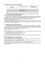
The pipe and fittings used in the piping system should meet the local requirements;
Pay attention to the maintenance and management of the piping system design, easy to operate and
adjust.
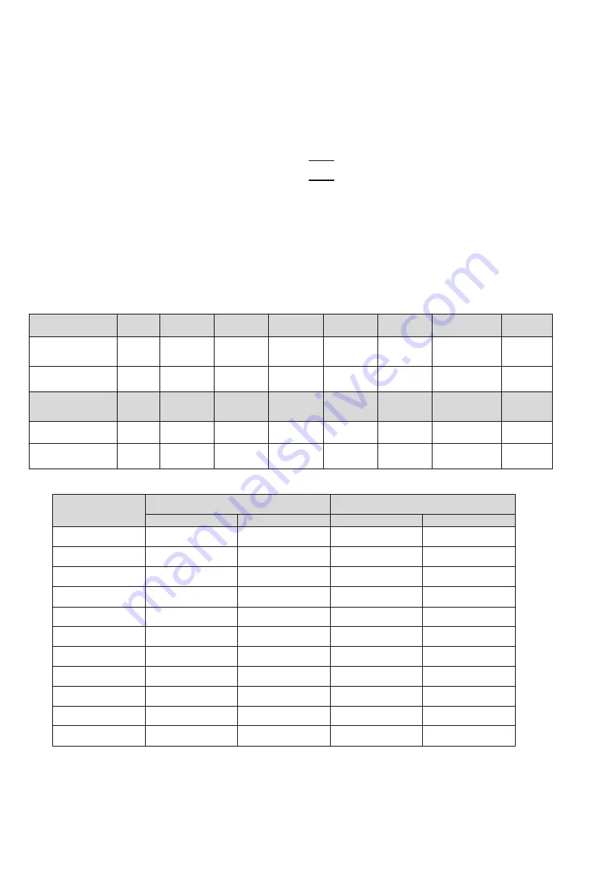
Determination of pipe diameter of air conditioning water system
The pipe diameter d is determined by the following formula:
d = √
4m
w
3.14v
In the middle
:
m
w
------Water flow
m
3
s
⁄
v
--------Water flow rate
m s
⁄
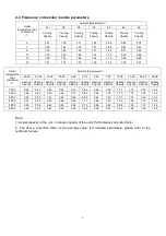
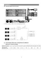
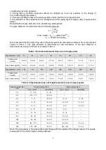
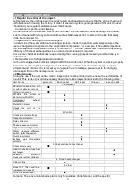
We recommend that the water flow rate in the water system be selected according to the recommended
values in Table 1. The pipe diameter is determined by trial calculation, or the pipe diameter is
determined according to the flow according to Table 2.
Table 1. Recommended water flow rate in the pipe (m/s)
Pipe diameter
(
mm
)
12
20
25
32
40
50
65
80
Closed water
system
0.4-0.5
0.5-0.6
0.6-0.7
0.7-0.9
0.8-1.0
0.9-1.2
1.1-1.4
1.2-1.6
Open water system 0.3-0.4
0.4-0.5
0.5-0.6
0.6-0.8
0.7-0.9
0.9-1.0
0.9-1.2
1.1-1.4
Pipe diameter
(
mm
)
100
125
150
200
250
300
350
400
Closed water
system
1.3-1.8
1.5-2.0
1.6-2.2
1.8-2.5
1.8-2.6
1.9-2.9
1.6-2.5
1.8-2.6
Open water system 1.2-1.6
1.4-1.8
1.5-2.0
1.6-2.3
1.7-2.4
1.7-2.4
1.6-2.1
1.8-2.3
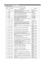
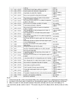
Table 2. Pipe diameter and unit length resistance loss of water system
Steel pipe diameter
(
mm
)
Closed water system
Open water system
flow
(
m3/h
)
kPa/100m
flow
(
m3/h
)
kPa/100m
15
0
~
0.5
0
~
60
--
--
20
0.5
~
1.0
10
~
60
--
--
25
1
~
2
10
~
60
0
~
1.3
0
~
43
32
2
~
4
10
~
60
1.3
~
2.0
11
~
40
40
4
~
6
10
~
60
2
~
4
10
~
40
50
6
~
11
10
~
60
4
~
8
--
65
11
~
18
10
~
60
8
~
14
--
80
18
~
32
10
~
60
14
~
22
--
100
32
~
65
10
~
60
22
~
45
--
125
65
~
115
10
~
60
45
~
82
10
~
40
150
115
~
185
10
~
47
82
~
130
10
~
43
Note: The parameters in the above table will change with the update of the design manual. For details,
please refer to the HVAC System Design Manual.
Содержание CA0065EANR
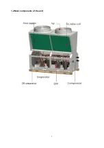
Страница 8: ...5 1 2 Main components of the unit ...
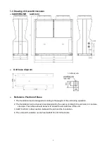
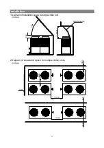
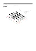
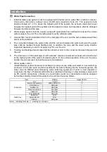
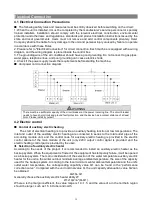
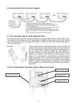
Страница 15: ...12 Installation 3 Diagram of arrangement of multiple chiller units Unit mm ...
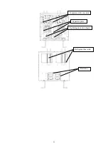
Страница 26: ...23 Compressor drive module Capacitor plate Lightning protection board Refrigerant heat sink Reactance ...
Страница 37: ......
Страница 38: ......
Страница 39: ......
Страница 40: ......


