background image


HAIER CHILLER 


Every indoor unit is connected to the individual controller or central controller through dual-core 
non-polar wire to realize the cental control. When one indoor starts up, the central air conditioning 
system will start up automatically. When all indoors arrive the set temperature, the master unit will stop. 
Energy saving.   

f.  Auto check technology: The system can check the operation status automatically; all kinds of sensors 

will transmit the operation parameters to the chip. By pressing the buttons, all the parameters can 
display on the liquid crystal screen. When the unit occurs failure in operation, the failure will display on 
the LED so that the malfunction can be solved soon. 

g.  Password control function: According to the user setting, the password control function can be used. 

Therefore the control to the unit will be more reliable and more flexible. 

h. 

Equipped with RS-485 physical connector, perfect network communication ability. 

i.  Module structure design, the system can be produced or transported as module unit. Every system is 

independent, and they are spare part for each other, however which cooling circuit is abnormal, the 
other systems do not be affected by the abnormal system, and furthermore they will run in shape. 
Module structure can reduce the cost of transport and installation greatly, more convenient. 

j. 

Heat exchanger of air side is designed much larger, enlarge heat transmission area, lower the 
temperature drop of transmission. Consequently, the chiller can run in cool mode even at high 
temperature of 45celsius degree in summer, and also can run in heat mode at low ambient temperature 
of –15celcius degree in winter with good performance. 

k. 

Safety and protection devices: phase reverse protection device, high and low pressure switch, freeze 
protection device, overheat protection device, overload protection device, etc. Also, with Timer ON/OFF, 
AUTO operation, defrosting, etc. functions. 


Содержание CA0035AANC

Страница 1: ...ir Cooled Module Water Chiller Installation operation and technical manual Heat pump Cooling only R22 refrigerant 33KW 65KW 3PH 380V 400V 50Hz Haier Commercial Air Conditioning MANUAL CODE SYJS 015 08REV 0 2008 12 05 ...

Страница 2: ...tric heating function control 12 10 Water pump operation control valid when water pump and the unit controlled simultaneously 12 11 The terminal simultaneous control 12 12 Wiring diagrams 13 13 Wired controller functions 15 14 Operation introduction 19 15 External wiring of UHR 820 type control board 22 16 Control functions 23 17 Controller specs 25 18 Malfunction and troubleshooting 25 19 Water q...

Страница 3: ...mpressors in parallel technology The master unit will control both compressors run or stop due to the water outlet temp Optimum refrigerant distribution technique and minimum deformation design Adoption of rolling bearing and non lubricated bearing Excellent heating effect at low temperature Broad range of working temperature and suitability for high condensation temperature c Shell Tube and U typ...

Страница 4: ...more flexible h Equipped with RS 485 physical connector perfect network communication ability i Module structure design the system can be produced or transported as module unit Every system is independent and they are spare part for each other however which cooling circuit is abnormal the other systems do not be affected by the abnormal system and furthermore they will run in shape Module structur...

Страница 5: ...g 420 410 755 735 Running weight kg 460 450 860 840 Nominal working condition cooling water inlet temp 12 water outlet temp 7 ambient temp 35 Nominal working condition heating water inlet temp 40 water outlet temp 45 ambient temp DB 7 WB 6 soft scroll cross finned coil inner grooved copper pipe dydrophilic aluminum finned coil shell tube heat exchanger working pressure 1 0MPa 2185 1000 1850 thermo...

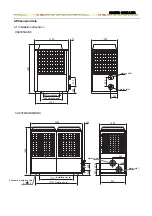
Страница 6: ...CA0070AANC MANC TLL RLL MTQL NRQ OQL OQL NQN MNLL MNQL SQ MLLL MTQL NLQL MOSQD MOMRD MOQ UOL MLLL PUT NQT NRQ OQL OQL NRQ P 6 M T Installation hole Hoisting hole water inlet water outlet Installation hole Hoisting hole water outlet water inlet Foundation installing hole ...

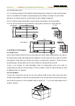
Страница 7: ... of which are the precise amount the unit operation needs When user receives the product he shall check it carefully to confirm if there is product damage in transportation and to confirm all the pre ordered parts are received If there is any damage he shall immediately inform the transportation person and claim for compensation according to relevant clauses If there is problem except for surface ...

Страница 8: ...tions of the Installation Standard for HV AC 5 4 8 The external water pipe system must be equipped with anti vibration hose water filter electronic water cleaner check valve drain valve discharging valve stop valve and expansion tank etc The expansion tank shall be installed 1 1 5m higher than the system top and its capacity is about 1 10 of the total water amount of the system The air release val...

Страница 9: ...gerant circuit may exceed 70 so that the untrained personnel shall not make bold to remove the protection panel of the unit 6 6 Unit shall not be installed in the air containing explosive gases 6 7 If the heat pump type unit operates under the condition below 0 it must be installed in a place 300mm higher than the ground which can not only prevent the bottom plate from freezing but also prevent th...

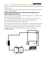
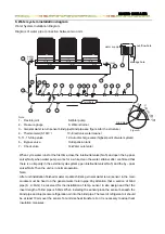
Страница 10: ...close the inlet outlet valve No 5 and open the by pass valve No 6 when water pump works for a while clean the water strainer after confirmed that there is no impurity in the external cycle system open inlet outlet valve No 5 and the by pass valve No 6 Then the unit is in normal operation Note After unit installation finished master module chiller s gerneral water return sensor in the main module m...

Страница 11: ...t When the unit is in standby state water pump will not start up when the unit enters working state from standby state start up water pump firstly when the unit enters standby state from working state or stop state 30seconds later water pump will stop automatically In stop state when water outlet temp is no more than 3 degree and more than 2 degree the water pump will start up when water outlet te...

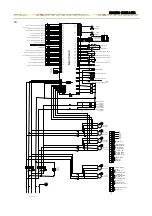
Страница 12: ... fan protection 485 communication DAH DAL high pressure switch low pressure switch linkage switch MCU M EEV JP18 EVA To next outdoor electric control system fan motor 3 M KM2 LDKG Cv flux switch X3 JP8 JP7 JP21 JP12 JK2 JK1 JK6 JK5 5A 250VAC Remark 1 Normal setting when out of factory fan protection linkage switch are short connected 2 There are not 4 way valve and relative accessories for cooling...

Страница 13: ... t Ta5 Ta6 Ta3 Ta4 Ta1 Ta2 Ta7 Te To Tr Tb7 Tb2 Tb1 Tb4 Tb3 Tb6 Tb5 assistant heater system B 4 way valve system A 4 way valve KM2 KM1 system B 1 compressor system B 2 compressor system A 2 compressor system A 1 compressor L4 L3 L2 L1 system B crankcase heater system B crankcase heater system A 2 crankcase heater system A 1 crankcase heater CC H4 CC H3 CC H2 CC H1 3 M 3 M 3 M KM1 KM2 KM3 CP2 FAN1 ...

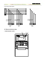
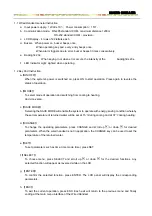
Страница 14: ...ons 1 WIRED HANDSET LAYOUT Set Temp 25 C Timer Mode Cooling 00 00 00 00 00 00 Sun INDICATOR POWER ON OFF MODE ERROR SAVE SET CHECK SELECT CHANGE ESC MODE ENTER S circuit breaker circuit breaker circuit breaker master unit slave unit 1 slave unit 15 R T R S T R S T R S T ...

Страница 15: ...ing to heating And vice versa c SAVE MODE Selecting the SAVE MODE will enable the system to operate with energy saving condition whereby the set temperature of returned water will be set at 15 during cooling and at 37 during heating d CHANGE To change the operating parameters press CHANGE and scroll up 5 or down 6 for desired parameters When the wired handset is not in application the CHANGE key c...

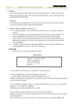
Страница 16: ...ng is allowed c To operate energy saving mode press SAVE MODE The returned water temperature for cooling operation will be set at 15 and at 37 for heating 2 MAIN MENU when power on The main display page is as follows MAIN DISPLAY 07 01 01 23 59 59 SUN Mode Cooling Heating Set Temp 25 Timer Sys Error First row display Year Month Day Hour minutes seconds weekday Second row display Mode setting Selec...

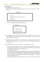
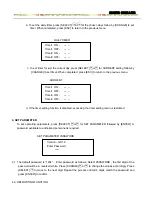
Страница 17: ...ESC to return to the previous menu 3 4 Press SELECT and scroll up 5or down 6 for Timer Press ENTER to confirm a To set weekly timer press SELECT to choose from Monday to Sunday Each day is allowed 2 settings of startup and shutdown To change the time press CHANGE and amend as desired When completed press ESC to return to the previous menu Detailed instruction as follows Press SELECT and scroll up ...

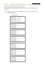
Страница 18: ...e continuous change of clock WEEKLY TIMER Mon Timer1 ON 00 00 Mon Timer1 OFF 01 00 Mon Timer2 ON 02 00 Mon Timer2 OFF 03 00 Tue Timer1 ON Tue Timer1 OFF Tue Timer2 ON Tue Timer2 OFF Wed Timer1 ON Wed Timer1 OFF Wed Timer2 ON Wed Timer2 OFF Thu Timer1 ON Thu Timer1 OFF Thu Timer2 ON Thu Timer2 OFF Fri Timer1 ON Fri Timer1 OFF Fri Timer2 ON Fri Timer2 OFF Sat Timer1 ON Sat Timer1 OFF Sat Timer2 ON S...

Страница 19: ...tricted 4 SET PARAMETER To set operating parameters press SELECT 5or6 for SET PARAMETER followed by ENTER A password available to authorized personnel is required SET PARAMETER PASSWORD 4 1 The default password is 1234 Enter password as follows Select PASSWORD the first digit of the password will be in reversed white Press CHANGE 5or 6 to change the values accordingly Press SELECT 6 to move to the...

Страница 20: ...FUNCTION Press SELECT to move to second parameter setting on safety SAFETY FUNCTION 1 To set the temperature of water out at which to trigger alarm press SELECT for Water out Alarm followed by CHANGE to set from 2 to 9 2 To set the lowest temperature of the returned water towards which the system will maintain press SELECT 5or6 for Set Temp Limit followed by CHANGE 5or6 to set from 5 to 12 Note To...

Страница 21: ...followed by CHANGE 5or6 to set from 01 to 16 If the parameter appears as the setting is invalid and is on self adaptive mode 2 To program the shutdown duration press SELECT 5or6 for Shutdown Parameter and repeat the above process 3 To access the manufacturer s setting press SELECT 5or6 for Mfg Parameter followed by ENTER and key in the password provided by the manufacturer MFG PARAMETER PASSWORD T...

Страница 22: ...for Language followed by Press CHANGE 5or6 to choose English Chinese d To set password press SELECT 5or6 for PASSWORD followed by ENTER Press SELECT 5or6 followed by CHANGE 5or6 to change the password from 0 to 9 Press ENTER to confirm and return to the main menu MFG PARAMETER PASSWORD When completed press ESC to return to the previous menu 4 To set password press SELECT 5or6 for PASSWORD followed...

Страница 23: ... restricted The default setting by the manufacturer is DISABLE b Press SELECT 5or6 to set for EXV2 Repeat the process as above c Press SELECT 5or6 for Set Frequency followed by CHANGE 5or6 to set the frequency of compressor from 15 110 Hz Press SELECT 6 and CHANGE 5or6 to set ENABLE if an inverter compressor is used If DISABLE is chosen the setting is invalid The default setting by Mfg is DISABLE ...

Страница 24: ...k the historical error record press ERROR for the menu ERROR RECORD The historical errors will be in chronological order Press SELECT and scroll up 5or down 6 to view the pages The panel display is according to year month day minute second module address and error code This function allows up to 28 errors to be recorded in chronological order and on first in first out basis To delete all records h...

Страница 25: ...x00 Parameter3 0x00 Parameter4 0x00 A system coil inlet 25 00 A system coil outlet 25 B system coil inlet 25 B system coil outlet 25 A system BPHE inlet 25 00 A system BPHE outlet 25 B system BPHE inlet 25 B system BPHE outlet 25 A system Suction 25 00 B system Suction 25 AC voltage 00 A System EXV 1500 B system EXV 1500 Press ESC to exit Total Comp 04 00 Comp Running 04 Total Module 01 ...

Страница 26: ...HAIER CHILLER PCB ...
Страница 27: ... unit 7 OFF ON ON ON slave unit 8 OFF ON ON OFF slave unit 9 OFF ON OFF ON slave unit 10 OFF ON OFF OFF slave unit 11 OFF OFF ON ON slave unit 12 OFF OFF ON OFF slave unit 13 OFF OFF OFF ON slave unit 14 OFF OFF OFF OFF slave unit 15 Notes module chiller can connect 16 pieces of units at the most to compose network Slave address setting had better set as sequence continuously 1 2 3 by turns adding...

Страница 28: ...HAIER CHILLER Sincere Forever Haier Group Haier Industrial Park No 1 Haier Road 266101 Qingdao China http www haier com ...

Отзывы: