background image

a PC for the first time, the appropriate standard drivers are loaded 
by the operating system.

The KE-USB108 emulates a standard 104  key USB keyboard, 
mouse and joystick.  The unit may be used in addition to or in 
place of the system’s own keyboard, mouse and joystick.

Interfacing to the KE-USB108 Input Headers

Switch Input Headers:
The KE-USB108 features three 2x20 headers for interface to 
switch input devices. The first header provides access to inputs 
1-36,  the second access to inputs 37-72 and the third access to 
inputs 73-108.  The input headers are arranged with Grounds on 
the two pairs of end pins on the headers, and the 36 inputs on 
the pins between them. The board is labeled near each header 
pin, designating the input number that the pin represents. Each 
of the pins may be programmed to emulate any standard PC 
keyboard key or key sequence,  as  well as joystick buttons or 
mouse buttons.

Inputs on the headers are activated by shorting them through a 
switch to any one of the provided logic Grounds on the header. 
When activated,  the input will report the keystroke,  mouse and 
joystick events that it has been programmed to emulate. If held 
active, the keystroke response will repeat (if programmed to repeat), 
based on the repeat rates and delays set within the PC operating 
system.  KE-USB108 inputs may be programmed to send keystrokes 
when the input is activated, deactivated, or both. The repeat of a 
key or key sequence is a selectable option for each input in the 
KE-USB108 configuration file.

The inputs are intended to handle mechanical switch inputs and 

5

30

Rotary Encoders:
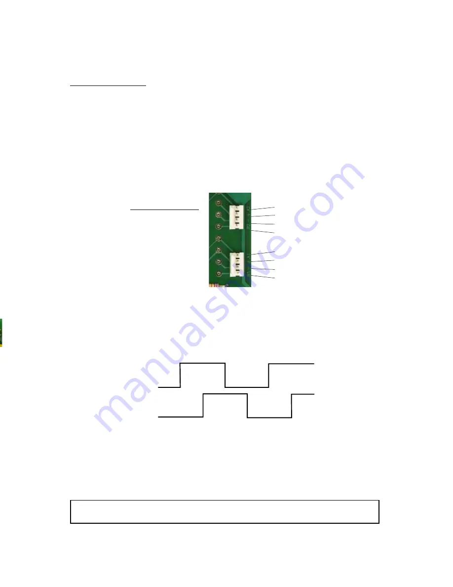
The KE-USB108 features two 4 position interface connectors which 
accept phased signals from a device such as a rotary encoder 
switch. 

Power is supplied to the rotary encoder switch from the
KE-USB108 for 5 volt operation only. This interface is compatible 
with mechanical and/or optical rotary encoder switches.

Use our MTA100-4-12 
cable to help connect from 
the KE-USB108 to a rotary 
encoder switch.  

Use the diagram to the 
right to make a connecting 
cable for a rotary encoder 
switch.

A2 = 2nd Rotary Sw. A Input

5V = Power for 2nd Rotary Sw.

GND = GND for 2nd Rotary Sw.

B2 = 2nd Rotary Sw. B Input

A1 = 1st Rotary Sw. A Input

5V = Power for 1st Rotary Sw.

GND = GND for 1st Rotary Sw.

B1 = 1st Rotary Sw. B Input

The KE-USB108 unit accepts input from mechanical and/or 
optical rotary encoders that produce a quadrature signal.

Typical Quadrature Signals 

from a Rotary Switch 

NOTE: Do not supply power to the rotary encoder switch interface connector.

Содержание KE-USB108

Страница 1: ...KE USB108 PC Keyboard Encoder User Manual ...

Страница 2: ...before using your KE USB108 In addition to this printed manual other resources are included with the product CD which provide information and tips on using the KE USB108 and making the most of it s features If you have any questions about the use of the KE USB108 not covered in this manual please contact us directly We offer toll free technical product support from 8 00am to 5 00pm M F Eastern Tim...

Страница 3: ...o Sequences Rotary Encoder Switches Trackball Control Spinner Control Joystick Axes File Menu Selections Error Messages KE USB108 Operating Tips Appendix A Specifications Appendix B KE USB108 Input Interface Appendix C KE USB108 Status LED Signals Appendix D Trackball Spinner Interface Appendix E Joystick Rotary Interface Accessories 3 3 4 5 9 10 13 16 18 19 20 20 22 23 25 26 27 28 29 31 2 ...

Страница 4: ...ovement selectable The KE USB108 is fully programmable by the user This programmability feature allows the configuration of various parameters as well as the selection of the keystrokes and button presses that will be sent to the PC The KE USB108 stores the user s configuration program in non volatile memory so that the information is retained on the unit even after power is turned off Power Requi...

Страница 5: ...ader for inputs 1 36 Dual Row 100 spaced pins 2x20 header X Y Z and Rx Joystick Potentiometer Headers 3 position MTA header 100 spaced pins Spinner Header and Trackball Header to emulate mouse movement A1 B1 Typical Quadrature Signals 2 Quadrature Rotary Encoder Inputs 4 position MTA header 100 spaced pins Trackball active high or low jumper select F u l l S p e e d U S B Spinner active high or lo...

Страница 6: ...r pin designating the input number that the pin represents Each of the pins may be programmed to emulate any standard PC keyboard key or key sequence as well as joystick buttons or mouse buttons Inputs on the headers are activated by shorting them through a switch to any one of the provided logic Grounds on the header When activated the input will report the keystroke mouse and joystick events tha...

Страница 7: ...kout board for screw terminal access to the KE USB108 input headers our part number IOX36 This interface board attaches to the KE USB108 headers through an IDE cable provided with the IOX36 See the Accessories page of this manual for details on the IOX36 Trackball Header The KE USB108 features an Input Header for connection to a Trackball We offer a Trackball Cable our part number KE TBH3 to conne...

Страница 8: ...00 3 12 to help connect the KE USB108 joystick input to the potentiometer See the Accessories page of this manual for details on the MTA100 3 12 A3 Spinner Signal 5V Spinner Voltage GND Spinner Ground B3 Spinner Signal A T T w T a P fr c S N th U to K U a 7 KE USB108 Joystick interface signal assignments NOTE Do not supply power to the joystick interface connectors KE USB108 Spinner interface sign...

Страница 9: ...nd stored in a safe location for future use 3 Open the folder that was created in step 2 and start the configuration program by selecting the program file KEUSB108 EXE Default Settings The KE USB108 is programmed and shipped with a default configuration Each input is configured to send its input number as keystrokes and then press enter For example input 100 will type 100 and then press enter By d...

Страница 10: ...Encoder Switch 2 Trackball Control Spinner Control and Joystick Axes as shown below Following is a list of each of the configuration sections along with an explanation of how they pertain to the KE USB108 setup Input Definitions The Input Definitions section of the main screen as shown to the left is used to define the keystrokes mouse button and joystick functions associated with each of the 108 ...

Страница 11: ... input first ensure that the Single Key option is selected for the input this is the default value Then click on the response definition box initially labeled Not Used This will open a window displaying a selection of keystrokes mouse buttons and joystick functions At the top of this dialog appear three tabs used to select between the type of response for that particular input Keyboard Tab The Key...

Страница 12: ...e being held The rate at which the key will repeat is determined by the repeat rate keyboard setting on your PC The key is released once the KE USB108 input becomes deactivated When the Key Repeat option is disabled this is the default value the keystroke is pressed and released upon input activation to produce a single keystroke Without the Key Repeat enabled only one keystroke or key sequence wi...

Страница 13: ...ponse to the input When a joystick button input is activated the selected button will remain pressed until the input is deactivated It is interesting to note that defining POV hat directions on two separate inputs can produce a POV hat diagonal For example if Input 1 is defined as north and Input 2 is defined as east then activating these inputs in unison will produce the direction s m e m a e r l...

Страница 14: ... up to 64 individual steps Each step of the macro can be defined as a key button press a key button release or a delay Clicking on a cell in the macro dialog will display a dialog for a selection of keystrokes mouse buttons and joystick functions Responses are selected by following the same procedures used for defining single keys on the preceding pages When creating macros the dialog contains add...

Страница 15: ...ill appear as shown below A programmed response is not needed for both the activation and deactivation sequences For example to send a B keystroke to the computer when the input is released program a press B under Step 1 of the deactivation sequence and a release B under Step 2 of the same deactivation sequence When defining a macro step an additional tab labeled Delay appears in the keyboard dial...

Страница 16: ...nwanted key mouse joystick or delay event 1 From the macro dialog click on the cell that contains the event to be deleted 2 Make sure the keyboard dialog is selected and if it is not then click the Keyboard tab 3 Click the Not Used button Macro Repeat In the lower left hand corner of the macro dialog is an option for repeating the activation sequence When the box marked Repeat activation sequence ...

Страница 17: ...epeated about twice a second This autofire function will continue until the input is released Rotary Encoder Switches The sections labeled Rotary Encoder Switch 1 and Rotary Encoder Switch 2 are used to configure the response from each of the rotary encoder switch inputs see below Individual keystrokes can be defined for both counterclockwise and clockwise rotation by clicking on the corresponding...

Страница 18: ...he rate is affected by other system actions therefore the selected rate is a maximum rate and not necessarily an absolute rate Divisor This option sets the number of incoming pulses the rotary encoder switch must provide per outgoing keystroke Many mechanical rotary encoder switches provide four pulses between each detent Setting this option to 4 will allow for such switches to produce one keystro...

Страница 19: ...a corresponding output pulse Rotary inputs are buffered up to 64 keystrokes per rotary encoder switch The buffer overflow option is selected by using the dropdown menu Valid selections are either disabled or enabled Trackball Control The section labeled Trackball Control is used for adjusting trackball movement Based on the type of trackball being used one or both of the Reverse Axis check boxes m...

Страница 20: ... and the pin to the left of the header active high Spinner Control The section labeled Spinner Control is used to adjust spinner use and movement The spinner can be defined to function as the mouse wheel or as either mouse axis This selection is made using the option buttons The spinner axis can also be reversed in the same manner as the trackball axes Spinner Jumper The KE USB108 provides a three...

Страница 21: ...s for each joystick axis By default all of the axes are disabled see the picture to the right Each axis can be individually enabled as needed by checking the Enabled Joystick Axis boxes Important Only select a particular joystick axis if that axis has a potentiometer connected to the corresponding KE USB108 joystick header File Menu Selections The file menu selections located within a dropdown lis...

Страница 22: ...rl S on the keyboard then choose a filename and location to save the file This option will read the current configuration in the KE USB108 and display it on the screen Click on Read from KE USB108 with the mouse or press Ctrl R on the keyboard to perform this operation Thisoptionwillwritethecurrentconfiguration displayed on the screen to the KE USB108 The KE USB108 can be programmed and re program...

Страница 23: ...USB108 This message indicates that while the computer can communicate with the KE USB108 it was not able to read the configuration If this error message is displayed read the configuration again If subsequent reads fail then write a new configuration Error while writing to the KE USB108 This indicates that while the computer can communicate with the KE USB108 it was not able to write the configura...

Страница 24: ...ould cause the computer to misunderstand further keystrokes a matching key release should be defined in nearly all circumstances KE USB108 Operating Tips When connecting the KE USB108 to a PC use a standard USB A B type Cable No changes will take place on the KE USB108 itself until the configuration has been written to the device Refer to section on File Menu Selections in this manual for details ...

Страница 25: ...24 d e s s s r y e t e o n n n d s Notes ...

Страница 26: ... Header 108 individual inputs divided between three 2 x 20 headers 025 square pins spaced at 100 Required Input Current 0 20 ma sink current typical Input Active Time The input must be active for at least 20 msec to be considered valid Note All dimensions are in inches 8 Mounting Holes 0 125 Diameter 4 300 7 750 0 200 0 190 0 810 to Center of USB Connector USB Connector Height 2 750 2 300 2 310 0 ...

Страница 27: ...he appropriate amount of time as listed in Appendix A The recommended maximum cable length from the KE USB108 input header to the input devices is 10 feet The recommended maximum cable length of the USB cable from the PC to the KE USB108 is 15 feet Note The KE USB108 allows any number of the 108 inputs to be activated simultaneously The response to each input will be processed in the order detecte...

Страница 28: ...leg to the inner pin of the signal pair and attaching the cathode leg of the LED to outer pin on the signal pair The outer pin is the pin closest to the outside edge of the KE USB108 No external current limiting resistors are required as they are supplied on the board Scroll Caps Num LED Circuit for use with the KE USB108 Inner Pin KE USB108 LED Signal on pin closest to outside edge of board Scrol...

Страница 29: ... market Note See sections Trackball Control and Spinner Control in the manual for active high or low jumper settings Use our KE TBH3 cable to connect from the KE USB108 directly to a Trackball or use our KE SP3 cable to connect from the KE USB108 directly to a Spinner Use the diagram below to make a connecting cable for a Spinner and or Trackball A1 Y axis signal 5V Power for Y axis GND Ground for...

Страница 30: ...atible with most popular potentiometer based joysticks Use our MTA100 3 12 cable to help connect from the KE USB108 to a joystick potentiometer Use the diagram to the right to make a connecting cable for a joystick potentiometer The potentiometer resistance must be between 10K ohms and 1M ohms Gnd for Rx axis Rx Input 5V Power for Rx axis Rx labeled W on board Gnd for Z axis Z Input 5V Power for Z...

Страница 31: ...ble to help connect from the KE USB108 to a rotary encoder switch Use the diagram to the right to make a connecting cable for a rotary encoder switch A2 2nd Rotary Sw A Input 5V Power for 2nd Rotary Sw GND GND for 2nd Rotary Sw B2 2nd Rotary Sw B Input A1 1st Rotary Sw A Input 5V Power for 1st Rotary Sw GND GND for 1st Rotary Sw B1 1st Rotary Sw B Input The KE USB108 unit accepts input from mechan...

Страница 32: ...ader through a standard IDE cable included Each input is brought out to a separate labeled screw terminal Use for solderless connection to the KE USB108 KE TBH3 KE USBMM6 6 ft Male Male Type A to Type B USB Cable f s s s Trackball interface cable This 3 foot cable attaches the KE USB108 Track ball input to the Trackball itself Custom lengths up to 10 feet are available ...

Страница 33: ...otary Encoder inputs 4 wires each 12 inches long MTA100 3 12 Cable set for use with KE USB108 Joystick inputs 3 wires each 12 inches long KE SP3 Spinner interface cable This 3 foot cable attaches the KE USB108 Spinner input to the Spinner itself Custom lengths up to 10 feet are available ...

Страница 34: ...output controls and display interfaces just to name a few Give us a call to discuss your custom requirements Special Output Controls LCD Interface LED Interface Serial Interface Questions or Comments Please give us a call Toll Free 888 690 9080 or visit us on the web www hagstromelectronics com email sales hagstromelectronics com 33 In C K In K D D R T S J F E K A A A A A A ...

Страница 35: ...ich you live you may have additional rights Great care has been taken during the assembly testing and burn in of your KE USB108 to ensure its performance If you have any questions please send us an email or give us a call Support is available Monday through Friday 8 00 am to 5 00 PM EST customer service email sales hagstromelectronics com Call Toll Free 888 690 9080 or 540 465 4677 NOTICE The KE U...

Страница 36: ...5 4677 Fax 540 465 4678 Monday through Friday 8 00 am to 5 00 PM EST sales hagstromelectronics com www hagstromelectronics com 1986 Junction Road Strasburg VA 22657 Copyright 2017 HAGSTROM ELECTRONICS INC V 07 16 HAGSTROM ELECTRONICS INC ...

Отзывы: