


Press
R
pushbutton once at TX100 learning
phase or for addressing in ETS.
O
In order to change the configuration mode,
a product "factory reset" is required
Input selection
In TX100 configuration mode, the selection or
numbering of the input is made by a short press
on key
A
.
Configuration
quick
link
&
See illustration
E
. Only the Up/Down type of com-
mand (green/red symbol) can be selected for the
KNX shutter actuators linked to the TRC321B. The
function obtained will correspond to that described
in illustration
D
.
Signal from indicator light
A
Factory reset
Keep pushbutton
R
down until the LED flashes
(>10s) then release it.
LED
cfg
turns off when factory reset is completed.
This operation deletes completely product configu-
ration. After factory return, wait 15s before doing a
new configuration.
Technical features
Power supply :
2 alkaline batteries
AAA LR03 1,5 V (lifetime ± 4 years)
Radio link :
868.3 MHz
Operating temperature :
0 °C à +50 °C
Storage temperature :
-25 °C à +70 °C
Mechanical protection class :
IP20 / IK04
Transmitter duty cycle :
1%
Receiver category :
2
Dimensions L x H x P :
138 x 26 x 31 mm
Weight (with batteries) :
70 g
Maximum output power :
25mW
Communication Media RF KNX :
RF1.R
Adjustment of the brightness setpoints
The brightness setpoints are adjusted using the
2 potentiometers. The colour of the
cfg
LED (see
illustration
D
) indicates that the result of a com-
parison between the brightness measured by the
sensor and the setpoint adjusted on the poten-
tiometer.
If, when the potentiometer is turned, the
cfg
LED begins to flash in two colours, this indicates
that the measured brightness corresponds to the
values set on the potentiometer, i.e.:
• Orange/green = setpoint
Ö
attained
• Orange/red = setpoint
É
attained
To take account of the conditions of installation
of the sensor, the adjustment is ideally made at a
time of day when the brightness corresponds to
the desired level (during the day and in the evening
if the 2 setpoints are used).
Saving and exit of the setting mode with short
presses on the key
A
or
J
.
Test mode
This allows accelerated testing of your program-
ming of
É
and/or
Ö
by simulating the desired
brightness levels.
- Long press > 10s on the
key
A
.
- The indicating lamp flashes
3x every 10s.
- The
Test
mode is activated
(5min. maxi).
- Deactivation: short press
on the key
A
.
The product operates with a measurement perio-
dicity reduced to 10 sec. instead of around
15 minutes (see illustration
D
).
Twilight and solar protection function
automation
The commands are sent by the TRC321B after a
brightness setpoint has been exceeded for around
15 minutes. (See illustration
D
)
Configuration
This transmitter may be configured in 3 different
ways :
•
quick
link
&
: configuration without tool, see
User's Instructions supplied with the radio trans-
mitters.
• E-mode TX100/B V.2.7.0 or > : Description of
product features is available from the manufac-
turer.
• S-mode ETS via TR131 : for ETS user, application
software STRC321B. Database and description of
software application available from the manufacturer.
Product description
A
Brightness detector TRC321B is a battery-powe-
red KNX radio transmitter. This product is intended
for shutter actuators. It controls the actuators in
accordance with the measured brightness and
the setpoints entered in the product, in order to
achieve protection from sunlight and/or to perform
the twilight function.
The measurement is carried out by a cell fixed by
a suction cup onto the inside of the window pane.
(Avoid any obstacles or dirt in front of the cell).
Functions
• Automatic control of shutters.
• Switch the Auto mode on/off by a short press
on key
A
.
• Potentiometer adjustment of the brightness
settings for solar protection
y
and / or for the
twilight function
o
.
• Deactivation of function
y
or
o
= Off position on
the potentiometer
y
or
o
).
The specific functions of this product are defined in
its configuration and set-up.
Opening
B
1
Unscrew the product using Phillips screwdriver.
2
Pull up the base guard.
3
Insert 2 alkaline batteries AAA LR03.
Battery change has no effect on product configu-
ration.
Fixing
Fix the base using 2 screws suited to the suppor-
ting materials or double-sided mounting tape.
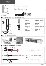
Fibre-optic cable connector
See illustration
C
.
Suction pad installation
The dimension
"X" determines
the maximal
stroke of pulling
down of the
shutters in case
of intensive
brightness.
x
pattes
de fixation
x
Befestigungseinheit
für Lichtleiter
x
latching
de ice
for fi re
+
Appui
simultané
sur
A
+
J
+ +
La LED clignote :
La fonction "réglage"
est activée
+
Gleichzeitiger
Druck auf
A
+
J
+ +
LED blinkt:
Einstellmöglichkeit
ist aktiv
+
Press on
simultaneously
A
+
J
+ +
The LED flashes :
The function “setting”
is activated
+ +
+
10s
10s
A
A
Empty batteries
Red flashing 1 sec.
Automatic mode
active
Signal on emission
- 4 flashing orange (pro-
duct not configured)
- Flashing green 100 ms
(product configured)
Changement de
mode par appui
sur touche
A
Auto
→
Stop
Stop
→
Auto.
- Lit red 1.5 sec.
- Lit green 1.5 sec.
L = 1,5 m
latching device for fibre
Press on
simultaneously
A
+
J
The LED flashes
:
The function “setting”
is activated
5
6LE003146A
Z
This device is to be installed only by
a professional electrician fitter according
to local applicable installation standards.
Conform to SELV installation rules.
Not to be installed outside.
Recommandations
Contact with the inside components may
damage the device due to static electricity
discharge.
When working on the device, apply the fol-
lowing rules at all times :
• avoid hand contact, or by means of a metal
tool, with the electronic components,
• use nonmagnetic tools,
• before reaching the internal components,
discharge your static electricity by touching
an unpainted metal surface such as a water
pipeline or a grounded electrical device.
Caution :
• The solar protection setpoint must not
be adjusted if the measured brightness
is > 1500 Lux.
• The twilight setpoint must not be adjusted if
the measured brightness is < 500 Lux.
• Between 500 and 1500 lux, the LED flashes
orange and neither of the 2 thresholds can be
adjusted.
Usable throughout Europe
å
and in Switzerland
Hager Controls hereby declares that the radio opening
detector device complies with the essential
requirements and other relevant provisions of Directive
2014/53/EU. The CE declaration is available
on the www.hagergroup.com site.


