background image

23

Rossi

Operating instructions − UTD.045.06-2013.00_TR_EN

TR

EN

of the parallel key is to be at least 0,9 times the pinion face width;

–  mount onto the servo motor shaft end, in the following order:
–   the 

spacer

 pre-heated at 

65 °C

 treating the relevant motor shaft 

area with 

adhesive type LOXEAL 58-14

 and checking that 

between keyway and motor shaft shoulder there is a cylindrical 

part ground by 1,5 mm at least; pay attention not 

to damage the 

external surface

 of spacer;

–   the 

key

 in the keyway, making sure that a contact length of at 

least 0,9 times the pinion width is present;

–   the 

pinion

 pre-heated at 

80 ÷ 100 °C

;

–   the 

axial fastening system

 when foreseen (self locking screw 

on motor shaft butt-end with washer and spacer or hub clamp 

with 1 or more dowels, fig. a); for the cases foreseen 

without 

axial fastening

 (fig. b), apply adhesive type 

LOXEAL 58-14

also on the motor shaft part laying under the 

pinion

;

–  in case of axial fastening system with hub clamp and dowels, 

make sure that they do not overhung from spacer external surface: 

screw the dowels completely and, if necessary, imprint the motor 

shaft with a point;

–  grease (with  grease type KLÜBER Petamo GHY 133N) the pinion 

teeth, the seal ring rotary seating and the ring itself, and assemble 

carefully, 

paying particular attention not to damage the seal 

ring lip due to an accidental impact with the pinion toothing

.

Servo gear reducer type R 

(servo motor coupling with bell and torsionally stiff coupling)

– 

Worm servo gear reducer R V, R IV

– 

Helical servo gear reducer R 2I, R 3I

– 

Bevel-helical servo gear reducer R CI, R ICI

The servo gear reducer 

type R input face has 

a flange (

bolts not 

included

) for servo 

motor mounting and a 

torsionally stiff coupling.
A half-coupling hub is to 

be fitted onto the servo 

motor keyless shaft end (if present, remove it; see fig. 1). In case of 

high starts/hour and heavy loads, it is necessary to request the non-

standard design

 «Coupling with keyway»

.

All mounting surfaces (shafts, bores, keys and keyways), must be 

clean and free of burrs, nicks and dents.
Check the servo motor shaft diameter, coupling bore diameter, key 

and keyway dimensions and tolerances.

All coupling bores are machined to tolerance H7

.

Assembling clearance between the servo motor shaft diameter and 

half-coupling hub diameter has to be maintained within 0,01 and 

0,05 mm.
A light coating of oil is recommended to ease the mounting process 

and will not affect the clamping force of the hub.
Do not use molybdenum disulphide or equivalent lubricants.

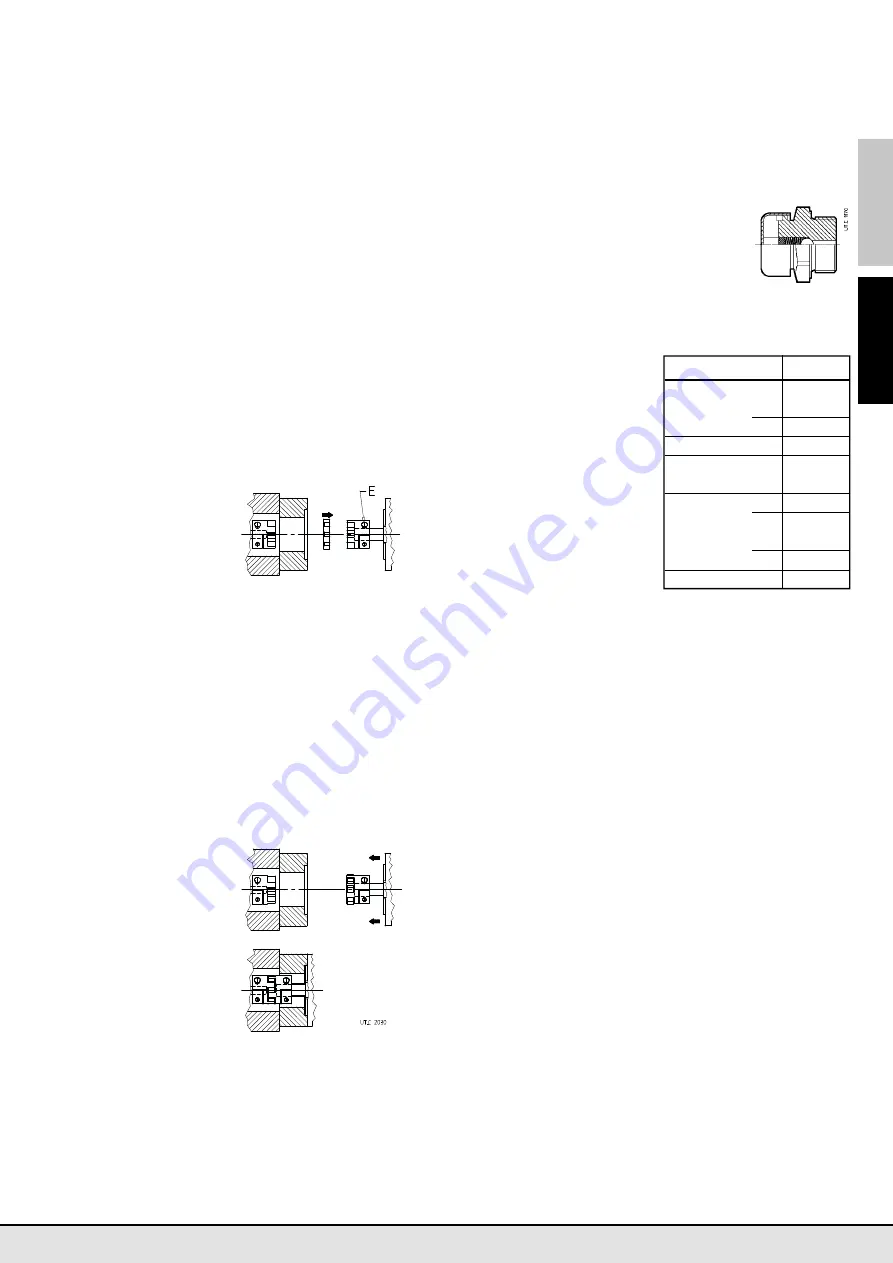
Insert the half-coupling onto the servo motor shaft, as shown 

in fig. 1, abutting with elastomer ring seat

Tighten the clamp 

screw 

E

, using a 

dynamometric wrench, 

to the appropriate 

torque stated in the 

table

1)

 (see page 24).

Clean the elastomer 

ring and the seats into 

the  coupling hubs 

and apply a light film 

of oil to facilitate the 

assembly process, see 

fig. 2 (use polyurethane 

compatible lubricants 

such as e.g. vaseline). 
Insert the elastomer ring 

(fig. 2) and assemble the 

servo motor on the servo gear reducer, tightening the screws (fig. 3) 

on the servo motor flange.

The achievement of the zero angular backlash is ensured by 

the squeezing of the elastomer ring interposed between the 

two parts of the coupling

.

1)   In some cases, a spacer to be interposed between the half-coupling and the servo 

motor shaft shoulder is provided

9.6 - Bearings

Since there are many different types of bearings in a gear reducer 

(roller, tapered roller, straight roller, etc.) and each bearing works 

fi g. 1

fi g. 2

fi g. 3

with different loads and speeds depending on the input speed, the 

nature of the load of the driven machine, the transmission ratio, 

etc., and with different lubricants (oil bath, oil splash, grease, oil 

circulation, etc.), it is not possible to define any periodical mainte-

nance and replacement of bearings in advance.
If a precautionally maintenance is required, 

undertake periodical 

checks to verify noise level and vibration with the help of 

appropiate diagniostic equipment and instruments

. If the 

measured values worsen even slightly it is necessary to stop gear 

reducer or gear motor and after having inspected inside the unit 

replace the bearings which are subject to breakdown.

9.7 - Metal filler plug with filter and valve

When the gear reducer or gearmotor (size ≥ 100) 

is equipped with metal filler plug with filter and 

valve (see fig. beside), in order to clean it, it is 

necessary to unscrew it from the gear reducer 

(preventing any debris or other foreign items 

from entering the reducer, disassemble the 

cover, wash it with solvent, dry with compressed 

air and reassemble it). 
This operation is to be made according to environment conditions.

10 - Sound levels

Most of the Rossi product 

range is cha 

racterised

by

sound pressure levels L¯

pA

(mean value of mea-surement, 

assuming nominal load and 

input speed 

n

1

 = 1 400 min

 -1

at 1 m from external profile of 

gear reducer  standing in free 

field on a reflecting surface, 

according to draft proposal 

ISO/CD 8579)

 lower or equal 

to 85 dB(A).

The table indicates the pro-

ducts which 

can exceed 

a.m. 

threshold. For further informa-

tion about sound levels of every 

single product see Rossi tech-

nical catalogs.

  Machine/Train of gears 

i

N

 Size

 Helical 

R I 

<

 3,15 

>

 160


>

 4 

>

 200


R 2I 

all 

>

 320


R 3I

 all 

>

 400


R 4I 

<

 160 

>

 500


>

 200 

>

 630

 Bevel helical 

R CI 

all 

>

 320


R C2I  <

 63 

>

 400


>

 71 

>

 500


R C3I 

all 

>

 630

 Bevel helical 

R C 

>

 250

Содержание Rossi MR V

Страница 1: ...Di li red kt rler ve motorlu red kt rler Gear reducers and gearmotors UTD 045 06 2013 00_TR_EN Kullan m talimatlar Operating instructions...

Страница 2: ......

Страница 3: ...a rlar ve bunlar icin ilave bilgiler gerekir Dikkat Montaj s ras nda elektrik motorunun standart frenli veya standart olmayan motor ve veya elektrik besleme cihaz Frekans d n t r c yumu ak kalk donan...

Страница 4: ...t r g vdesi zerindeki delikler veya vidal delikler kullan lmal d r Kald rma s ras nda y k n dengeli olarak da lmakta ve sapanlar n yeterli mukavemette oldu u teyit edilmelidir Gerekti inde di li red k...

Страница 5: ...nze ri par alar hasarlanabilir Kama ba lant l H7 m6 ve K7 j6 ba lant l par alar n tak lmas nce sinde 80 ila 100 C seviyesinde s t lmalar gerekir D d 11 4 00 M 5 14 19 M 6 24 28 M 8 30 38 M 10 42 55 M...

Страница 6: ...P MOBIL Glygoy e SHELL Omala S4 WE KL BER Kl bersynth GH 6 kullan l r SENTET K YA LE DOLU SHELL Gadus S5 V142W00 IP Telesia Compound A MOBIL Glygoyle Grease 00 Filtre tahliye tapas sadece Koaksiyal ti...

Страница 7: ...alel ve dik a l milli di li red kt rler i indir R I R 2I MR 2I R 3I MR 3I MR 4I Paralel B31 B7 B6 B31 B62 B7 B31 B6 B7 B31 B6 B7 V53 ebat B81 V5 V6 B81 V5 V6 B81 V53 V6 B81 V6 40 00 0 4 0 9 0 55 0 47...

Страница 8: ...n derilmi oldu unda ya dolumu Al c ya ait olacakt r bu durum ya g stergesinden anla labilir Di li red kt r zerinde bir ya lama plakas yer almaktad r Di li red kt r tipine g re ya tipi veya miktar ya t...

Страница 9: ...eviyeye kadar di li red kt r n doldurun Her zaman ke eleri de i tirmeniz nerilir b l m 9 3 e bak n Kep s k lmesi s ras nda kep tak lm di li red kt rlerde temizlenmi ve gresi giderilmi y zey zerine yap...

Страница 10: ...r yard mc motor montaj sistemi kullanman z onerilir Servo di li red kt r tipi MR do rudan servo motor kaplini tipi Sonsuz servo di li red kt r MR V Helisel servo di li red kt r MR 2I Konik helisel ser...

Страница 11: ...ek derecede hafif bir ya katman nerilir Molibden dis lf r veya e de eri ya lay c lar kullanmay n Yar m man onu tablo 1 de g sterildi i ekilde servo motor aft zerine tak n elastomer halka yata ile biti...

Страница 12: ...60 320 Dik a l kat L 80 125 Suda erir poliakrilik ift bile enli emaye Di li red kt r n kaplin y zeyle rindeki olas boyalar bir spatula veya solvent ile kart n Osadzane na wale Wsp osiowe2 56 142 ift b...

Страница 13: ...a nm ar zal veya yetersiz ya lama Rossi ye ba vurun Di li red kt r konumu duzeltin Tapa ya ka r yor Ya ok fazla Ya seviyeni miktar n kontrol edin Yanl montaj konumu Ya so utma sistemi yetersiz veya d...

Страница 14: ...and bevel helical size MR 3I 50 Helical and bevel helical size MR 3I 63 1 1 Valid only for sizes 140 360 Takma ek 4a ve s kme ek 4b Sonsuz di li b y kl kleri 32 50 Paralel ve dik a l aft b y kl 50 So...

Страница 15: ...accessories if any flow indicators independent cooling unit thermostat ecc con sult the attached specific documentation If necessary require it Attention For any clarification and or additional inform...

Страница 16: ...with the motor and the driven machine with the aid of shims if need be for gear reducers size 400 use level tapped holes interposing flexible couplings whenever possible Incorrect alignment may cause...

Страница 17: ...sc springs into the reaction recess Concerning the reaction system follow the project indications sta ted in the technical catalogs Rossi Whenever personal injury or property damage may occur foresee...

Страница 18: ...Energol SG XP MOBIL Glygoyle SHELL Omala S4 WE KL BER Kl bersynth GH6 having the ISO visco sity grade given in the table FILLED WITH SYNTHETIC GREASE SHELL Gadus S5 V142W00 IP Telesia Compound A MOBIL...

Страница 19: ...d L an for non continuous duties 1 Not stated on name plate 2 Values valid for R 2I for MR 2I the values are respectively 0 8 1 2 2 3 3 The first reduction stage the first two for 4I is lubricated wit...

Страница 20: ...the obtained level by oil outlet When gear reducer or gearmotor is provi ded with a level plug with rod fill with oil up to specified level on rod When gear reducer or gearmotor is sup plied with a le...

Страница 21: ...n hollow high speed shaft of gear reducer Worm gearmotors MR V Helical gearmotors MR 2I MR 3I 140 360 Bevel helical gearmotors MR CI MR C2I be sure that the mating surfaces are machined under accuracy...

Страница 22: ...r with the servo gear reducer if necessary adjust it accordingly to the servo motor shaft keyway length position the gear reducer vertically with motor mounting flange upwards see fig 2 rotate the hub...

Страница 23: ...n in fig 1 abutting with elastomer ring seat Tighten the clamp screw E using a dynamometric wrench to the appropriate torque stated in the table1 see page 24 Clean the elastomer ring and the seats int...

Страница 24: ...yn thetic oils polyalphaolefines synthetic oils are suitable Remove by a scraper or solvent the possible paint of gear reducer coupling surfaces Coaxial type 50 81 Helical and bevel helical 100 631 Co...

Страница 25: ...cessive load during running in Excessive ambient temperature Check oil level gear reducer at rest or quantity lubricant type and or state see ch 6 2 lubrication table replace if necessary Change mount...

Страница 26: ...IT EN IT EN Notlar Notes...

Страница 27: ......

Страница 28: ...the accuracy of the information contained in this publication however Rossi can accept no responsibility for any errors omissions or outdated data Due to the constant evolution of the state of the art...

Отзывы: