96-0012 rev G
7
June 2003
O
M
PERATOR’S
ANUAL
A u t o m a t i c
A u t o m a t i c
A u t o m a t i c
A u t o m a t i c
P a l l e t C h a n g e r
P a l l e t C h a n g e r
5th Axis
Port
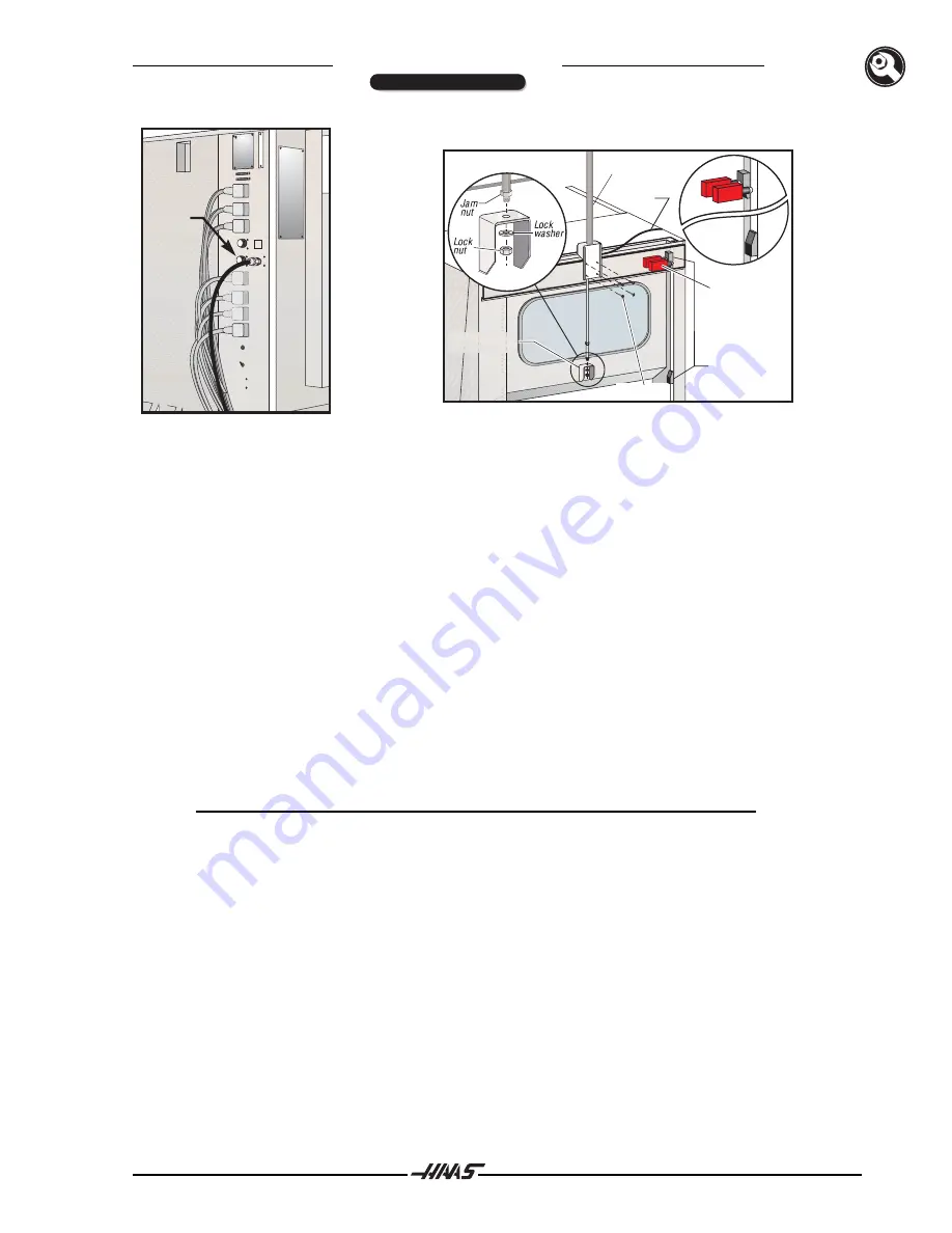
Door Bracket
Air Line
Door
Switches
Air Cylinder
BHCS (4)
Trip
Blocks
Figure 3.2 Fifth Axis port on the side of the
Figure 3.3 Air cylinder installation.
VMC control cabinet
Installing Door Air Cylinder
3.
Remove the lock nut and washer from the end of the air cylinder rod, but leave the jam nut in place.
Connect the automatic door air cylinder and bracket to the machine with four 1/4"-20 BHCS, as
shown in Figure 3.3.
4.
Insert the air cylinder rod into the door bracket, then attach the lock nut and washer to the bottom
of the cylinder rod.
5.
Install the door switches and bracket onto the VMC with two SHCS each. Insert the door air line
into the fitting at the base of the air cylinder.
6.
POWER ON the VMC and ZERO RETURN all axes. Verify that the VMC operates normally.
7.
In MDI mode, command an M17. The table will unclamp (raise) and the automatic door will open.
The door and table will stay up. Clean all shipping protectant from the rollers, alignment pins and
clamp bars.
NOTE
:
M14 will move the table slowly in case a pallet is present.
Positioning the APC
8.
Raise the APC with the forklift and install the leveling screws into the legs. As a preliminary height
setting, turn the screws until the length of screw extending above the APC leg is the same as the
length of VMC leveling screw extending above the VMC base. Set the leveling pads (3) in place.
9.
Set the APC in place on the leveling pads, so that it is centered in the VMC door opening (see
Figure 3.4). Ensure that the lip of the APC enclosure is centered in the VMC drip trough (see
Figure 3.5).
INSTALLATION


