background image

1-4 

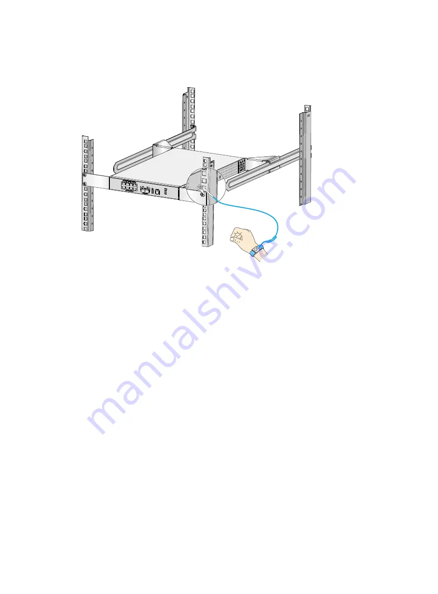
4. 

Attach the alligator clip to the rack. 

5. 

Make sure the rack is reliably grounded. 

Figure1-2 Attaching an ESD wrist strap (WX3010H-X-PWR) 


EMI 

All electromagnetic interference (EMI) sources, from outside or inside of the device and application 
system, adversely affect the device in the following ways: 


A conduction pattern of capacitance coupling. 


Inductance coupling. 


Electromagnetic wave radiation. 


Common impedance (including the grounding system) coupling. 

To prevent EMI, use the following guidelines: 


If AC power is used, use a single-phase three-wire power receptacle with protection earth (PE) 
to filter interference from the power grid. 


Keep the device far away from radio transmitting stations, radar stations, and high-frequency 
devices. 


Use electromagnetic shielding, for example, shielded interface cables, when necessary. 


To prevent signal ports from getting damaged by overvoltage or overcurrent caused by lightning 
strikes, route interface cables only indoors. 

Lightning protection 

To better protect the device from lightning, follow these guidelines: 


Make sure the grounding cable of the chassis is reliably grounded. 


Make sure the grounding terminal of the AC power receptacle is reliably grounded. 


Install a lightning protector at the input end of the power module to enhance the lightning 
protection capability of the power module. 

Содержание WX3000H series

Страница 1: ...H3C WX3000H Series Access Controllers Installation Guide New H3C Technologies Co Ltd http www h3c com Document version 6W103 20200228...

Страница 2: ...respective owners Notice The information in this document is subject to change without notice All contents in this document including statements information and recommendations are believed to be acc...

Страница 3: ...keywords or arguments that are optional x y Braces enclose a set of required syntax choices separated by vertical bars from which you select one x y Square brackets enclose a set of optional syntax c...

Страница 4: ...switch such as a Layer 2 or Layer 3 switch or a router that supports Layer 2 forwarding and other Layer 2 features Represents an access controller a unified wired WLAN module or the access controller...

Страница 5: ...Documentation feedback You can e mail your comments about product documentation to info h3c com We appreciate your comments...

Страница 6: ...ng the device 2 10 Optional Installing network port lightning protectors 2 12 Optional Installing a surge protected power strip 2 13 Connecting interface cables 2 13 Connecting the console cable and s...

Страница 7: ...PWR 5 1 WX3010H L PWR 5 2 WX3024H 5 3 WX3024H L PWR 5 3 Interface numbering 5 4 WX3010H 5 4 WX3010H X PWR 5 4 WX3010H L PWR 5 4 WX3024H 5 5 WX3024H L PWR 5 5 Technical specifications 5 5 Transceiver m...

Страница 8: ...re from entering the device chassis Ensure good ventilation of the equipment room and keep the air inlet and outlet vents of the device free of obstruction Make sure the operating voltage is in the re...

Страница 9: ...kage mechanical property change of materials and metal corrosion Lasting low relative humidity can cause washer contraction and ESD and cause problems including loose mounting screws and circuit failu...

Страница 10: ...ines Ground the device and rack or workbench reliably Take dust proof measures for the equipment room For more information see Cleanliness Maintain the humidity and temperature at acceptable levels Fo...

Страница 11: ...with protection earth PE to filter interference from the power grid Keep the device far away from radio transmitting stations radar stations and high frequency devices Use electromagnetic shielding f...

Страница 12: ...3010H WX3010H X PWR WX3010H L P WR Cage nut 4 user supplied 8 user supplied 4 user supplied M6 rack screw 4 user supplied 8 user supplied 4 M4 mounting bracket screw 8 16 4 M3 mounting bracket screw N...

Страница 13: ...g bracket screw 4 N A M3 mounting bracket screw N A 8 M4 shoulder screw for weight bearing 2 N A Rubber feet 1 set 1 set Grounding cable 1 1 Console cable 1 1 AC power cord 1 1 Bail latch 1 1 Front mo...

Страница 14: ...ures are taken for filtering interference from the power grid The protection ground of the device is away from the grounding facility of power equipment or lightning protection grounding facility The...

Страница 15: ...opriate for the device The front and rear of the rack are a minimum of 0 8 m 31 50 in away from walls or other devices Safety precautions The device is far away from any moist area and heat source You...

Страница 16: ...f you want to open the chassis contact H3C Support for permission Otherwise H3C will not be liable for any consequence caused thereby Confirming installation preparations Before you install the device...

Страница 17: ...on flow Figure2 1 Installation flow Mounting the device on a workbench CAUTION Do not place heavy objects on the device If a standard 19 inch rack is not available you can mount the device on a clean...

Страница 18: ...nch WX3010H X PWR Installing the device in a 19 inch rack Installation methods Table2 1 Installation methods for the access controllers Device model Installation method Using front and rear mounting b...

Страница 19: ...N A N A WX3024H N A WX3024H L P WR N A N A Installing cage nuts Before mounting the device in a rack install cage nuts on the rack To install cage nuts 1 Wear an ESD wrist strap and make sure the rac...

Страница 20: ...al plane Figure2 4 Cage nuts on the same horizontal planes Rack mounting the device by using front and rear mounting brackets and slide rails A WX3010H X PWR access controller uses front and rear moun...

Страница 21: ...device 3 Use M4 screws supplied with the rear mounting brackets to attach the rear mounting brackets to the device Figure2 6 Attaching the rear mounting brackets to the device 4 Use M6 rack screws and...

Страница 22: ...rackets to the front rack posts as shown in Figure2 8 Make sure the device is installed securely in the rack Figure2 8 Installing the device in the rack by using front and rear mounting brackets and s...

Страница 23: ...Attach the M4 shoulder screws supplied with the rear mounting brackets to the device The M4 shoulder screws are used for weight bearing See Figure2 10 for the installation position Figure2 10 Attachin...

Страница 24: ...kets for rack mounting To attach front mounting brackets to a WX3010H access controller see Rack mounting the device by using front and rear mounting brackets and slide rails To attach front mounting...

Страница 25: ...ghtning rod The following procedure uses the WX3010H X PWR access controller as an example To ground the device 1 Use a Phillips screwdriver to remove the grounding screw from the chassis 2 Use the gr...

Страница 26: ...n reliably grounded Figure2 15 Grounding the device with the rack Grounding the device with a grounding conductor buried in the earth If earth is available at the installation site hammer a 0 5 m 1 64...

Страница 27: ...he device Purchase them yourself as required To install a network port lightning protector for a network port 1 Use a double faced adhesive tape to stick the network port lightning protector onto the...

Страница 28: ...if required To use a surge protected power strip first connect the AC power line routed from outdoors to the strip and then connect the power cord from the device to the strip You can attach the surge...

Страница 29: ...fiber excessively The bend radius of an optical fiber must be not less than 10 cm 3 94 in Keep the fiber end clean Make sure the Tx and Rx ports on a transceiver module are connected to the Rx and Tx...

Страница 30: ...r cord CAUTION Before connecting the AC power cord make sure the device is reliably grounded To connect the AC power cord 1 Pivot the bail latch upward 2 Connect one end of the AC power cord to the AC...

Страница 31: ...o an RPS 1 Verify that the device is powered off and the RPS is switched off 2 Use a Phillips screwdriver to remove the screws on the cover on the DC power receptacle and take off the cover 3 Connect...

Страница 32: ...ory and runs the BootWare The following information appears on the terminal screen BootWare Validating Press Ctrl B to access EXTENDED BOOTWARE MENU 2 Press Ctrl B at the prompt within 4 seconds to ac...

Страница 33: ...condition 4 If the issue persists contact H3C Support Software loading failure Symptom The device fails in software loading Solution To resolve the issue 1 Verify that the physical ports are connected...

Страница 34: ...ends on the software and hardware version of the device H3C display version H3C Comware Software Version 7 1 064 ESS 5118 Copyright c 2004 2020 New H3C Techbologies Co Ltd All rights reserved H3C WX30...

Страница 35: ...a Execute the tar extract command to extract the gz file from the tar gz file b Execute the gunzip command to unzip the gz file c Execute the more command to view the file contents Display the operati...

Страница 36: ...l The device is operating correctly Max Ports Maximum number of ports supported Displaying the electronic label data for the device An electronic label is a profile of a device It contains the permane...

Страница 37: ...CPU usage in the last 5 minutes after the device boots the device calculates and records the average CPU usage at intervals of 5 minutes Displaying the memory usage of the device Use the display memor...

Страница 38: ...ly Abnormal The fan is faulty or is not present Displaying the operating state of power modules Use the display power command to display the operating state of power modules H3C display power Power 1...

Страница 39: ...nformation about the display startup command see configuration file management commands in H3C Access Controllers Fundamentals Command Reference For more information about the display boot loader comm...

Страница 40: ...orts 9 and 10 3 1000BASE X SFP ports 11 and 12 combo ports 4 100 1000BASE T autosensing Ethernet ports 11 and 12 combo ports 5 USB port 6 Console port Figure5 2 Rear panel 1 AC power receptacle 2 Grou...

Страница 41: ...10H L PWR Figure5 5 Front panel 1 100 1000BASE T PoE autosensing Ethernet ports 1 through 8 2 100 1000BASE T autosensing Ethernet ports 9 and 10 3 1000BASE X SFP ports 11 and 12 4 USB port 5 Console p...

Страница 42: ...t ports 27 and 28 combo ports 5 USB port 6 Console port Figure5 8 Rear panel 1 DC power receptacle 2 AC power receptacle 3 Grounding screw WX3024H L PWR Figure5 9 Front panel 1 100 1000BASE T PoE auto...

Страница 43: ...time Ports marked 1 to 10 are LAN ports Ports marked 11 and 12 are WAN ports WX3010H X PWR Ports on a WX3010H X PWR access controller are numbered as follows Ports marked 1 through 8 are 2 5G 1000 10...

Страница 44: ...20 are 100 1000BASE T PoE autosensing Ethernet ports represented by interface number GigabitEthernet 1 0 1 through GigabitEthernet 1 0 20 respectively Ports marked 21 through 24 are combo ports repres...

Страница 45: ...C 50 60 Hz Max voltage range 90 to 264 VAC 47 to 63 Hz DC input voltage Rated voltage range 54 to 57 VDC Max voltage range 44 to 60 VDC System power consumption 64 W to 103 W Number of ports that supp...

Страница 46: ...1000BASE T PoE autosensing Ethernet port SFP port 2 10G 1GBASE R SFP SFP autosensing port 2 combo 1000BASE X SFP port Memory 2GB DDR3 Storage media 2 8MB NOR flash 1GB NAND flash Dimensions H W D exc...

Страница 47: ...4 VAC 47 to 63 Hz DC input voltage Rated voltage range 54 to 57 VDC Max voltage range 44 to 60 VDC System power consumption 19 W to 31 4 W Number of ports that support PoE 22 Max output capacity per P...

Страница 48: ...nsceiver module Figure5 13 Optical fiber with LC connectors 1 LC connector 2 Optical fiber Transceiver module specifications The transceiver modules whose names contain MM and SM support multi mode op...

Страница 49: ...E see Table5 17 WX3010H L PWR SFP GE SX MM850 A see Table5 7 SFP GE LX SM1310 A see Table5 8 SFP GE LH40 SM1310 see Table5 9 SFP GE LH40 SM1550 see Table5 10 WX3024H SFP GE SX MM850 A see Table5 7 SF...

Страница 50: ...m Table5 9 SFP GE LH40 SM1310 specifications Item Specification Central wavelength 1310 nm Max transmission distance 40 km 24 86 miles Data rate 1250 Mbps Connector type Duplex LC Fiber mode SMF Fiber...

Страница 51: ...0 specifications Item Specification Central wavelength 1310 nm Max transmission distance 220 m 721 78 ft Data rate 10 31 Gbps Connector type Duplex LC Fiber mode MMF Fiber diameter 62 5 m Transmit pow...

Страница 52: ...ns Item Specification Central wavelength 1310 nm Max transmission distance 10 km 6 21 miles Data rate 10 31 Gbps Connector type Duplex LC Fiber mode SMF Fiber diameter 9 m Transmit power 8 2 to 0 5 dB...

Страница 53: ...ns Item Specification Central wavelength 850 nm Max transmission distance 300 m 984 25 ft Data rate 10 31 Gbps Connector type Duplex LC Fiber mode MMF Fiber diameter 50 m Transmit power 7 3 to 1 dBm R...

Страница 54: ...vertemperature has occurred Off The system is not operating or is in reset state AC power status LED PWR Steady green AC power is being input and the power module is operating correctly Steady red The...

Страница 55: ...ort is receiving or transmitting data at 1000 Mbps Steady yellow A 100 Mbps link is present on the port Flashing yellow The port is receiving or transmitting data at 100 Mbps Off No link is present on...

Страница 56: ...00 BASE T PoE autosensing Ethernet port status LED N A Steady green A 2 5 Gbps link is present on the port Flashing green The port is receiving or transmitting data at 2 5 Gbps Steady yellow A 1000 or...

Страница 57: ...ff No PoE ports are outputting power Ethernet port status LED Link Act Steady green A 1000 Mbps link is present on the port Flashing green The port is sending or receiving data at 1000 Mbps Steady yel...

Страница 58: ...er correctly Flashing green A PoE port is outputting power incorrectly or is overloaded Off No PoE ports are outputting power 100 1000BASE T autosensing Ethernet port status LED N A Steady green A 100...

Страница 59: ...SYS Table6 5 LED description LED Mark Status Description System status LED SYS Flashing green 4 Hz The system is loading software Flashing green 0 5 Hz The system is operating correctly Steady red A s...

Страница 60: ...green A 1000 Mbps link is present on the port Flashing green The port is sending or receiving data at 1000 Mbps Steady yellow A 100 Mbps link is present on the port Flashing yellow The port is receiv...

Отзывы: